Dynamic Cross Axis Coupling Compensation in High Temperature Multi Axis Gyroscope Calibration Rigs
Real-time matrix inversion compensating thermal frame tilt and encoder phase lag restores multi-axis gyroscope dynamic cross-axis isolation up to 200°C.


Kinematics
Axis alignment on multi-axis rate tables deteriorates rapidly under severe thermal stress. Motion simulators carrying multi-axis gyroscopes into heated test cells face substantial structural distortion. When an outer gimbal sweeps at 300 degrees per second while the thermal chamber operates at 175°C, thermal expansion across steel or aluminum support yokes alters the physical mounting angles between gantry axes.
This angular tilt produces cross-coupling torque, generating false rate signals on orthogonal sensor channels.

Gantry Thermal Deformation Dynamics
Structural frame expansion displaces bearing centerlines. As temperatures climb from ambient levels to 200°C, uneven thermal gradients develop across gantry arms, bearing journals, and motor mounts. Differential expansion between inner and outer gantry rings converts nominal orthogonality errors into temperature-dependent misalignment matrices.
An axis tilt of just 0.5 milliradians introduces a cross-axis angular rate signal equal to 0.05 percent of the off-axis rotation speed; at high angular velocities, this crosstalk quickly swamps the bias drift floor of tactical-grade sensors.
At 200°C, structural expansion across a 500 mm aluminum gimbal generates up to 1.2 mrad of axis tilt.
Acceleration Induced off Axis Errors
Rotational acceleration generates inertial torque that deflects cantilevered gantry supports. During dynamic motion profiles, rapid speed changes on the roll axis induce transient bending across the pitch and yaw gimbals. Elevated chamber temperatures soften structural alloys, compounding this mechanical compliance.
The resulting structural flexure skews the true angular rate vector applied to the unit under test, pulling the physical drive axis out of alignment with the calibrated encoder axis.
Neglecting structural deflection during thermal rate sweeps leads to corrupted sensor scale-factor calibrations, forcing expensive re-qualification cycles when fielded units fail navigation accuracy benchmarks.
Orthogonality
Mechanical misalignments between direct-drive motor shafts introduce phase-lagged rate crosstalk during multi-axis sweeps, requiring a time-variant matrix transformation across both temperature and frequency domains. While direct drives avoid gear-train hysteresis, thermal expansion shifts shaft centerlines. Consequently, the physical coupling matrix must account for nominal geometric misalignment angles, thermal distortion coefficients, and velocity-dependent dynamic compliance terms.

Dynamic Decoupling Matrix Construction
Real-time processing models the true angular velocity vector from measured motor encoder rates against instantaneous gantry temperatures. The measured motion vector passes through an inverted alignment matrix updated continuously at loop rates up to 10 kHz. Misalignment coefficients expand into Taylor series polynomials driven by surface-mounted resistance temperature detectors placed across the gantry frame.
Cross Axis Coupling Failure Modes
Without active compensation, multi-axis motion rigs exhibit several distinct distortion pathways during high-temperature calibration runs.
- Thermal Frame Warpage shifts shaft orthogonality beyond nominal mechanical alignment limits during rapid temperature ramping above 150°C.
- Gimbal Bearing Compliance permits shaft tilt under high angular acceleration, causing rate leakage into orthogonal measurement axes.
- Phase Mismatch In Encoder Signals delays real-time matrix inversion, generating high-frequency residual ripple during high-rate rate sweeps.
- Drive Shaft Torsional Deflection introduces velocity-dependent phase lags between drive motors and payload mounting plates.
Thermal equilibrium across inner and outer gantry structures requires multi-hour soak times per temperature step.
Rig designers continue to debate whether low-order polynomial matrix transformations can adequately capture non-linear mechanical resonances excited at specific thermal thresholds.


Chamber
Enclosing a three-axis motion simulator inside a environmental enclosure creates steep thermal gradients. Radiative heat transfer from heating elements raises outer gantry surface temperatures while interior motor shafts lag behind. Even where Invar frames help preserve structural geometry, direct motor heat generation combines with ambient chamber heating to produce localized thermal pockets that shift mechanical alignment unpredictably.
Material Selection for Thermal Stability
Selecting structural alloys with low coefficients of thermal expansion limits frame growth under thermal stress. Substituting Invar or low-expansion ceramics for conventional aluminum alloys stabilizes frame dimensions across a 220°C operational window.
| Material Grade | CTE (ppm/K at 20°C to 200°C) | Thermal Conductivity (W/m·K) | Elastic Modulus (GPa) |
|---|---|---|---|
| Invar 36 Alloy | 1.2 | 10.1 | 141 |
| Silicon Nitride Ceramic | 3.2 | 30.0 | 310 |
| 6061-T6 Aluminum | 23.0 | 167.0 | 68.9 |
| 316 Stainless Steel | 16.0 | 16.3 | 193 |
Thermal Profiling Procedure
Executing precise calibration across wide temperature ranges follows a structured environmental sequence.
- Mount the sensor suite to the inner gimbal interface plate using thermally isolated titanium fasteners.
- Equilibrate the enclosure at the baseline temperature of 25°C for 60 minutes to establish reference optical encoder zero points.
- Ramp chamber temperature at 2°C per minute while driving all axes at low rotational rate to maintain uniform thermal distribution.
- Dwell at target thermal plateau for 180 minutes until structural frame temperature sensors report drift under 0.1°C per 15 minutes.
- Execute multi-axis sinusoidal rate sweeps while recording optical encoder positions and sensor output streams.
Direct-drive brushless motors eliminate mechanical hysteresis while introducing localized heat sources into the payload mounting plate.
Platform specifications rate thermal axis drift within operational limits, while bench-level cross-axis contamination is frequently attributed to ambient room fluctuations or ducting faults.

Feedback
High-frequency angular position tracking relies on optical encoder scales mounted directly to the inner gimbal, where scale resolution defines the baseline measurement floor. Position readings route through optical fiber links to external processing electronics, protecting sensitive conversion circuitry from high chamber temperatures.

Can Encoder Latency Corrupt Real Time Matrix Inversion?
Serialization delays in position datastreams create phase lag between actual gantry position and the mathematical matrix update cycle. At angular velocities of 500 degrees per second, a 100-microsecond latency in signal transmission produces a spatial error of 0.05 degrees. This phase shift degrades cross-axis compensation filter performance, injecting false high-frequency corrections into the motion control loop.
| Error Source | Physical Mechanism | Uncompensated Error Impact | Compensated Residual Error |
|---|---|---|---|
| Thermal Gantry Tilt | Asymmetric arm expansion | 1.2 mrad / 100°C | 0.03 mrad |
| Encoder Latency Lag | Data serialization delay | 0.05 deg at 500 deg/s | 0.002 deg |
| Bearing Thermal Preload | Differential inner ring growth | 0.4 mrad shaft runout | 0.02 mrad |
| Motor Cable Windup Torque | Harness stiffness change | 0.15 N·m dynamic resistance | 0.01 N·m |

Signal Processing Architecture
Digital signal processors read optical encoder edges, compute temperature-compensated position vectors, and update transformation matrices every 100 microseconds. Because hardware bandwidth constrains real-time correction, filtering high-frequency encoder noise without introducing group delay requires custom finite impulse response filters tuned directly to gantry anti-resonance frequencies.
- Encoder Interface Selection specifies high-temperature optical heads rated for continuous 200°C operation without signal amplitude attenuation.
- Fiber Optic Data Links eliminate electromagnetic interference generated by pulse-width modulated direct-drive motor amplifiers inside the chamber enclosure.
- Thermal Sensor Integration places platinum RTDs within 5 mm of axis bearing journals to track real-time gradient formation.
- Real Time Processor Sizing selects field-programmable gate arrays capable of parallel matrix multiplication loops under 20 microseconds.
ISO 16063-13 mandates transducer cross-axis sensitivity measurement below two percent across the entire operating dynamic range.
Meeting ISO 16063-13 requires explicit reporting of cross-axis coupling uncertainty across the full operating thermal range, invalidating test certificates that rely solely on ambient static orthogonality calibrations.


Verification
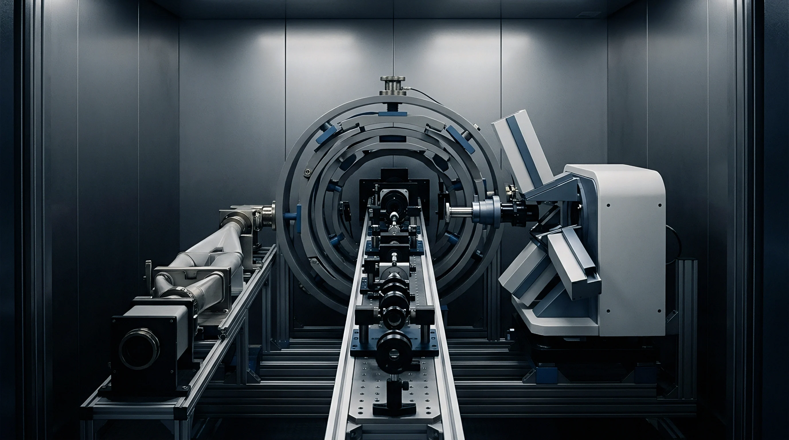
Evaluating residual crosstalk following dynamic matrix compensation requires an independent optical reference. External autocollimators and laser interferometers target the gantry through quartz chamber windows to verify pointing accuracy under thermal load. Because bearing runout corrupts transformation calculations, ceramic air bearings are often required to maintain shaft stiffness.
These optical checks confirm whether the transformation matrix successfully cancels mechanical frame tilt across multi-axis rate profiles.
Laser Interferometric Validation Procedures
Laser tracking systems follow corner-cube retroreflectors mounted on the payload table throughout multi-axis motion cycles. Comparing optical position vectors with gantry encoder output isolates mechanical hysteresis, thermal frame expansion, and drive shaft deflection terms. Residual angular errors measured after compensation establish the absolute physical baseline of the calibration gantry.
Quantifying Residual Matrix Drift
Tracking orthogonality drift across multi-hour thermal soak profiles identifies unmodeled higher-order temperature terms that would otherwise shift sensor calibration curves. Updating lookup table interpolations prevents long-term systematic drift from degrading sensor acceptance testing thresholds.
System validation concludes by loading residual alignment maps directly into motion controller memory. These calibration tables apply static offset limits during high-rate testing, ensuring the platform delivers clean single-axis rate inputs to the unit under test even while operating at maximum thermal limits.