Quantifying Hydrostatic Pressure Coefficients in Deep Ocean Conductivity Sensor Calibration Documentation
Quantifying conductivity cell hydrostatic coefficients requires empirical hyperbaric autoclave testing to prevent abyssal salinity biases exceeding 0.006 PSU.


Geometry
Deep ocean conductivity measurement rests on the physical dimensions of an electrolytic cell. Oceanographic conductivity cells channel seawater through an internal bore where platinum electrodes measure electrical conductance. The cell factor expresses the ratio of path length to cross-sectional area.
In ambient bench conditions, this geometry remains stable. Downward transit into the abyss exposes the assembly to extreme hydrostatic forces. Pressure deforms the measurement path.
Hydrostatic load compresses the cell walls, shortening the axial length and constricting the interior diameter.
Standard oceanographic data processing resolves conductivity through an empirical polynomial corrected for environmental distortions. The governing relation expresses conductivity as a function of raw sensor output frequency, cell temperature, and hydrostatic pressure:
C = (g + h f^2 + i f^3 + j f^4) / (10 (1 + ctcor T + cpcor P))
The variable C represents electrolytic conductivity in Siemens per meter, f denotes the digitized output frequency in kilohertz, T is water temperature in degrees Celsius, and P denotes hydrostatic pressure in decibars. The terms g, h, i, and j serve as primary polynomial calibration coefficients established in atmospheric seawater baths. The coefficient ctcor compensates for thermal expansion of the cell substrate.
The coefficient cpcor compensates for volumetric cell compression under hydrostatic load.
Glass contracts under hydrostatic load. For an unconstrained, isotropic hollow cylinder subjected to uniform hydrostatic pressure, linear elasticity dictates that all linear dimensions shrink in direct proportion to the bulk compressibility of the material. When axial length contracts by a fractional amount and cross-sectional area contracts by twice that fractional amount, the geometric ratio of length to area expands.
The cell factor increases under pressure. Uncorrected sensor output records an artificial elevation in conductivity. The empirical coefficient cpcor enters the denominator with a negative sign to nullify this geometric contraction.
A borosilicate cell under six thousand decibars of hydrostatic pressure contracts its internal volume by roughly two parts per thousand.
Calibration documentation from commercial oceanographic instrument builders routinely enters a fixed theoretical value for cpcor. The standard documented value for borosilicate glass conductivity cells sits at -9.57e-8 per decibar. This number originates from laboratory measurements of the compressibility of bulk Pyrex published in the mid-twentieth century.
Commercial calibration certificates reproduce this exact exponent across entire production batches over multiple decades. The certificate documents g, h, i, and j to eight significant digits based on live bath measurements, yet leaves cpcor as an unmeasured constant. Cell mounts introduce mechanical constraint.
Epoxy potting, silicone isolation sleeves, and titanium pressure housing collars restrict uniform radial and axial strain. The actual mechanical deformation of an assembled conductivity cell diverges from idealized bulk glass compressibility.
Manufacturers explain that separate hydrostatic pressure testing for individual production sensors adds prohibitive capital expense while introducing contamination risks to the delicate platinum black coating on internal electrodes.

Bath
Primary calibration of oceanographic conductivity sensors takes place in temperature-controlled seawater circulation baths at atmospheric pressure. The metrology requires absolute temperature stability, uniform salinity distribution, and direct traceability to primary standards. Standards laboratories maintain multiple open baths containing natural seawater adjusted to salinities ranging from 0 to 42 Practical Salinity Units.
Automated chilled and heated fluid jackets hold thermal stability within 0.0005 degrees Celsius over multi-hour calibration cycles.
Transfer standards govern the bath reference values. Standard Platinum Resistance Thermometers calibrated on the International Temperature Scale of 1990 monitor the bath temperature with expanded uncertainties below 0.0008 degrees Celsius. Discrete fluid samples drawn during the calibration run undergo analysis on benchtop salinometers standardized against International Association for the Physical Sciences of the Oceans standard seawater.
Standard seawater ampoules trace their electrical conductivity ratio directly to primary potassium chloride solutions prepared at national metrology institutes. The resulting atmospheric conductivity reference achieves an expanded uncertainty of 0.0003 Siemens per meter.
Factory baths run at surface pressure. Atmospheric tanks cannot reproduce the physical forces present at abyssal depths. The calibration protocol measures sensor frequency across five or six distinct temperature and salinity setpoints, all conducted at zero decibars gauge pressure.
The least-squares regression solver fits the primary coefficients g, h, i, and j exclusively to these surface measurements. The thermal coefficient ctcor is evaluated by varying temperature while holding salinity constant. The pressure coefficient cpcor drops out of the regression matrix completely because the pressure term remains identically zero throughout the procedure.
The absence of hydrostatic pressure during primary certification forces the documentation to rely on nominal material properties. Different structural materials exhibit distinct compressibility profiles, listed in the technical baseline below.
| Substrate Material | Bulk Modulus (GPa) | Thermal Expansion ctcor (1/C) | Nominal cpcor (1/dbar) | Coefficient Uncertainty (1/dbar) |
|---|---|---|---|---|
| Borosilicate Glass (Pyrex 7740) | 39.5 | 3.25e-6 | -9.57e-8 | ±1.20e-8 |
| Synthetic Fused Silica (Quartz) | 36.9 | 0.55e-6 | -1.02e-7 | ±0.85e-8 |
| High-Purity Alumina Ceramic (99.8% Al2O3) | 228.0 | 6.50e-6 | -1.46e-8 | ±0.25e-8 |
| Titanium Grade 5 Housing Mount | 113.8 | 8.60e-6 | -2.93e-8 | ±0.40e-8 |
Compression shrinks the internal bore. When an instrument deploys to abyssal depths, an unquantified shift in the true pressure coefficient translates directly into profiling bias. At six thousand decibars, an error of 1.0e-8 per decibar in the assigned cpcor generates an artificial salinity error of approximately 0.006 on the practical salinity scale.
Modern oceanographic research programs targeting abyssal circulation and heat uptake demand salinity measurements accurate to within 0.002 Practical Salinity Units. A batch-averaged, unverified cpcor consumes three times the total allowable error budget of the entire measurement program.
Application of an inaccurate hydrostatic pressure coefficient creates an artificial salinity offset that deep ocean monitoring programs cannot distinguish from true water mass freshening.
Deep ocean gradients demand proof. Relying on nominal documentation values shifts the burden of proof from factory quality assurance to post-voyage oceanographic data reconciliation. Uncorrected pressure dependencies corrupt deep potential temperature and salinity relationships, rendering baseline data unusable for multi-decadal climate comparisons.
Rig
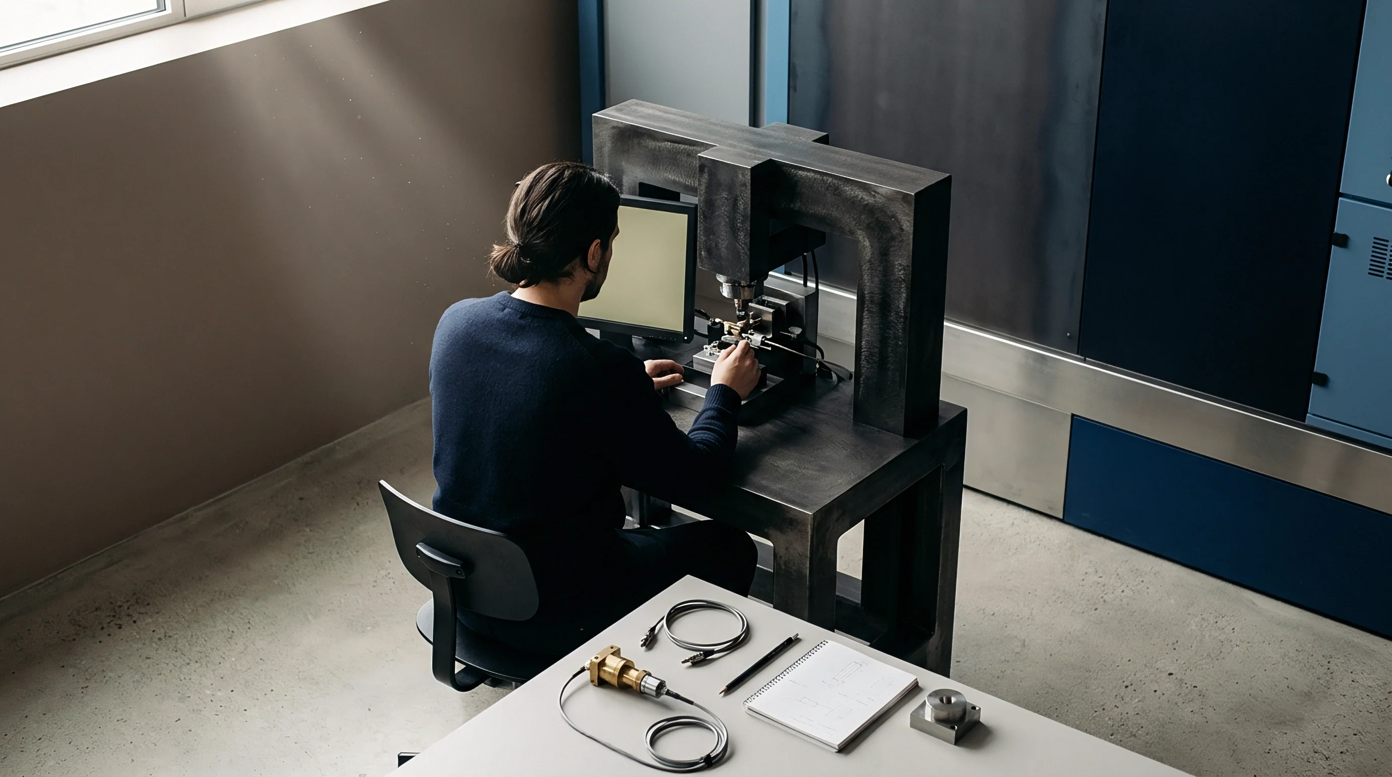
Empirical quantification of sensor behavior under load requires specialized hyperbaric testing installations. Specialized pressure calibration facilities combine high-pressure autoclaves with recirculating fluid systems capable of maintaining stable temperature and salinity under cyclic hydrostatic loading up to one thousand bar. The metrology demands precise control over secondary thermodynamic effects that arise during fluid compression.
Compression heats the pressure vessel. Rapid pressurization of liquid causes adiabatic heating, raising the bath fluid temperature by several tenths of a degree Celsius per thousand decibars. A hyperbaric calibration test requires substantial thermal stabilization periods at each pressure plateau to permit thermal equalization between the fluid, the heavy vessel walls, and the sensor housing.
Without complete dissipation of adiabatic heat, temperature gradients across the conductivity cell mimic pressure-induced geometry changes, corrupting the extraction of cpcor.
Execution of a pressure coefficient calibration follows an explicit physical cycle:
- The technician installs the conductivity sensor inside a titanium or stainless-steel hyperbaric test vessel filled with homogeneous, degassed seawater of known practical salinity.
- The chamber fluid circulates through an external heat exchanger until internal temperature sensors demonstrate thermal equilibrium within 0.002 degrees Celsius over a thirty-minute window.
- Primary pressure standards, consisting of a deadweight tester or a calibrated resonant quartz pressure transducer, log the vessel baseline pressure at atmospheric level.
- Hydraulic pumps inject fluid to raise chamber pressure in discrete increments of one thousand decibars up to the full working limit of the sensor.
- The system pauses at each pressure plateau for forty-five minutes, logging cell output frequency, reference temperature, and hydraulic pressure once thermodynamic stability recovers.
- Hydraulic valves release pressure along an identical step sequence to record decompression response and quantify mechanical hysteresis in the cell mounting.
Raw frequencies tell another story. Data logged across the pressurization and depressurization cycles separates pure elastic deformation from viscous relaxation in cell seals. Borosilicate glass demonstrates negligible mechanical hysteresis, returning to baseline dimensions within seconds of depressurization.
Elastomeric O-rings and polyurethane potting compounds, however, exhibit time-dependent viscoelastic creep. In sensors where the external jacket contacts the measuring volume, this mechanical creep produces an apparent drift in conductivity that decays over hours.
| Hydrostatic Pressure (dbar) | True Cell Factor Shift (%) | Conductivity Error at -0.5e-8 Bias (S/m) | Salinity Error at -0.5e-8 Bias (PSU) | Salinity Error at -1.5e-8 Bias (PSU) |
|---|---|---|---|---|
| 1000 | +0.010 | -0.00015 | -0.0015 | -0.0044 |
| 2000 | +0.019 | -0.00030 | -0.0029 | -0.0088 |
| 3000 | +0.029 | -0.00045 | -0.0044 | -0.0131 |
| 4000 | +0.038 | -0.00060 | -0.0058 | -0.0175 |
| 5000 | +0.048 | -0.00075 | -0.0073 | -0.0219 |
| 6000 | +0.057 | -0.00090 | -0.0088 | -0.0263 |
The error scales with depth. The table shows that even a modest discrepancy of 0.5e-8 per decibar exceeds the GO-SHIP program threshold of 0.002 Practical Salinity Units before the instrument reaches two thousand decibars. When a sensor encounters full trench depths of six thousand decibars with an uncalibrated discrepancy of 1.5e-8 per decibar, the resulting salinity error surpasses 0.026 Practical Salinity Units.
Procurement specifications referencing WOCE or GO-SHIP data thresholds mandate documented hyperbaric validation of cell coefficients for all instrumentation deployed below two thousand meters.
Contractual acceptance clauses demanding compliance with deep hydrography standards reject certificates that derive cpcor strictly from literature constants. When procurement agreements enforce hyperbaric validation clauses, vendors must append empirical pressure-run logs to the final calibration dossier.
Budget
Quantifying the hydrostatic pressure coefficient requires a complete measurement uncertainty analysis conforming to the Guide to the Expression of Uncertainty in Measurement. The combined standard uncertainty of cpcor integrates contributions from reference thermometry, hydraulic pressure measurement, fluid homogeneity, reference salinity determination, and cell mathematical modeling. A single uncorrected temperature drift inside the hyperbaric chamber propagates into the pressure coefficient with severe magnification.
Seawater conductivity exhibits high thermal sensitivity. At typical deep-sea temperatures near two degrees Celsius, electrical conductivity changes by roughly two percent per degree Celsius. A temperature measurement error of 0.005 degrees Celsius inside the test autoclave mimics a conductivity shift of 0.0001 Siemens per meter.
If this thermal error correlates with pressure steps due to insufficient dissipation of adiabatic heat, the regression algorithm attributes the conductivity shift to geometric cell deformation. The extracted cpcor absorbs the thermal measurement defect directly into its numerical value.
| Uncertainty Component | Standard Uncertainty u(xi) | Probability Distribution | Sensitivity Coefficient ci | Uncertainty Contribution (1/dbar) |
|---|---|---|---|---|
| Autoclave Reference Temperature | 0.0015 °C | Normal (k=1) | 5.8e-7 (1/dbar °C) | 8.7e-10 |
| Hydraulic Pressure Transducer | 1.2 dbar | Normal (k=1) | 1.6e-11 (1/dbar^2) | 1.9e-11 |
| Fluid Salinity Stability | 0.0010 PSU | Rectangular | 5.2e-7 (1/dbar PSU) | 3.0e-10 |
| Adiabatic Non-Equilibrium Residual | 0.0020 °C | Rectangular | 5.8e-7 (1/dbar °C) | 6.7e-10 |
| Cell Mounting Viscoelastic Creep | 0.00008 mS/cm | Normal (k=1) | 4.2e-6 (1/dbar mS/cm) | 3.4e-10 |
| Regression Fit Residual | 0.00005 mS/cm | Normal (k=1) | 4.2e-6 (1/dbar mS/cm) | 2.1e-10 |
Uncertainty expands at depth. Combining the variance components through root-sum-square summation yields an expanded uncertainty for cpcor of approximately 2.6e-9 per decibar at a ninety-five percent confidence level with a coverage factor of k = 2. When an engineering dossier delivers an empirical cpcor without a supporting uncertainty budget, the reported value lacks metrological standing.
Thorough calibration documentation contains explicit structural elements:
- Traceable Reference Instrumentation identifying serial numbers, calibration dates, and national laboratory certificate references for all thermistors and quartz pressure transducers installed inside the hyperbaric loop.
- Thermal Equilibrium Criteria detailing the exact settling times, residual thermal drift rates, and stability thresholds enforced at each pressure dwell.
- Hysteresis Quantification Logs comparing ascending and descending pressure traverses to document mechanical recovery of elastomeric seals and glass housings.
- Regression Residual Distributions showing the numerical spread between raw observed conductivities and model-fitted conductivities across the complete pressure range.
Empirical determination of hydrostatic pressure coefficients achieves an expanded uncertainty of 2.6e-9 per decibar under rigorous hyperbaric laboratory controls.
Field data audits reveal that slight variations in glass tube wall thickness across manufacturing lots shift the empirical cpcor across a span exceeding 5.0e-9 per decibar. Whether commercial instrument suppliers will eventually incorporate serial-specific hyperbaric testing into routine production lines remains an open industrial question.

Cast
When factory calibration documentation omits empirical pressure validation, oceanographers quantify and verify cpcor through deep hydrographic casts. Deep research vessels collect reference data by lowering an instrument rosette equipped with primary CTD sensors, secondary backup sensors, and a carousel of Niskin bottles to full ocean depth. Bottle samples triggered at the bottom of the cast capture pristine deep seawater for immediate analysis on benchtop salinometers.
The deep ocean serves as a stable metrological comparator.
Abyssal water masses exhibit exceptional temporal stability. In regions such as the North Pacific Deep Water and the deep Argentine Basin, potential temperature and salinity relationships remain virtually invariant over decadal timescales. Water properties below four thousand decibars vary by less than 0.001 Practical Salinity Units across large geographic basins.
By projecting CTD conductivity measurements from deep casts into temperature-salinity space, metrologists detect pressure-dependent systematic deviations against historical reference curves.
The resulting salinity shifts negative. If the documented cpcor assumes an idealized compression that underestimates true cell shrinkage, the computed salinity drifts downward as depth increases. Oceanographic analysts calculate the optimal cpcor correction by executing an iterative residual minimization between downcast sensor conductivity and bottle sample conductivity:
Residual = C_measured / (1 + delta_cpcor P) – C_bottle
Consider an operational scenario comparing factory documentation against deep bottle data. A research consortium deploys twenty deep profiling floats rated to four thousand decibars. The factory documentation provides a uniform nominal cpcor of -9.57e-8 per decibar.
During shipboard calibration casts prior to float deployment, comparison against Niskin bottle salinities analyzed on a Guildline 8400B Autosal reveals a consistent negative salinity offset at four thousand decibars averaging -0.0048 Practical Salinity Units. The observed deep offset indicates that the true cpcor of the float sensor batch averages -8.75e-8 per decibar rather than the nominal documented value.
Adjusting the calibration dossier post-cruise requires re-processing raw frequency archives across the entire fleet. The engineering hours required to recalculate millions of profile observations exceed the cost of specifying certified hyperbaric calibration during original equipment procurement. Sourcing departments that reject documentation lacking empirical hyperbaric proof avoid extensive retrospective data corrections.
A documented calibration certificate without empirical pressure verification represents an incomplete specification.
Sensor purchasers evaluate the financial balance between upfront hyperbaric certification fees and downline data reclamation expenses. Experienced oceanographic procurement specialists observe that unverified physical coefficients documented at the factory inevitably demand verification at sea.