Polymer Creep Verification Methods in Sensor Adhesives
Polymer creep in sensor adhesive joints degrades span and zero-point calibration; verification requires deadweight shear or dynamic mechanical master curves.

Bond
The stability of a bonded sensor hinges on how effectively mechanical strain moves across its adhesive joint. Sensing elements ~ whether piezoresistive silicon dies, metal foil strain gauges, or piezoelectric ceramic discs ~ require a rigid load path to convert mechanical deformation into resistance or charge. Over time, sustained mechanical stress deforms the adhesive layer.
Viscoelastic flow inside the polymer network bleeds off internal stress, reducing the strain that reaches the sensing grid and showing up at the instrument output as zero drift or decaying span calibration.
Designing transducers involves balancing two contradictory material behaviors. Rigid substrates like precipitation-hardened 17-4 PH stainless steel or 7075-T6 aluminum spring elements undergo almost no time-dependent deformation at room temperature below their elastic limits. Organic polymers, however, continuously rearrange their molecular chains under static stress as secondary bonds break and reform under sustained shear.
Unfilled bisphenol-A epoxy systems show a typical creep error of 0.05% of full-scale output after 1,000 hours at 70 degrees Celsius under a 40 MPa shear load. Based on standard 12-coupon isometric testing batches evaluated in 2022, dropping the post-cure thermal dwell below 80 degrees Celsius doubles this unrecoverable deformation within 200 hours of installation.
Primary creep in structural joint adhesives produces sensor zero-point drift before macro-yield occurs.
Adhesive thickness scales interfacial creep displacement directly. While a thinner joint creates a steeper shear gradient, it reduces the total volume of viscoelastic material subject to molecular redistribution. Bondlines thicker than 50 micrometers exhibit higher signal attenuation under continuous load.
Adding mineral fillers like colloidal silica or aluminum oxide particles restricts chain motion and aligns thermal expansion coefficients more closely with metallic adherends, lowering bulk thermal expansion.

Mechanics of Interfacial Strain Attenuation
Interfacial shear stress concentrates heavily near the outer edges of a bonded gauge or die. Classic shear-lag modeling shows that peak shear loads develop at the active element boundaries and decay exponentially toward the center. As the adhesive undergoes creep relaxation, this shear stress peak broadens and shifts inward, effectively shortening the active gauge length of the sensing element.
Crosslink density ultimately dictates long-term compliance.
- Viscoelastic strain lag attenuates mechanical transmission from the deflecting beam to the sensing grid over extended holding intervals.
- Interfacial slip generates non-linear zero return offsets following peak proof-overload cycles on the test bench.
- Plasticization from moisture ingress depresses the polymer glass transition temperature toward ambient operating thresholds.
- Asymmetric thermal contraction generates micro-cracking across heavily filled mineral interfaces during rapid thermal shock sequences.
Extended load dwell causes unrecoverable chain slippage, while thin glue lines restrict lateral strain relief. Formulation choices ultimately determine whether initial transient creep stabilizes or degrades into steady-state secondary deformation.

Viscoelastic Relaxation under Continuous Sensor Preload
Sustained preloads are common in pressure sensor diaphragms clamped by threaded rings, load cells carrying structural tare weights, and torque transducers under permanent bolt tension. In these configurations, the adhesive joint experiences continuous multi-axial shear. Standard ambient qualification testing often misses slow relaxation mechanisms that only become apparent months into field service.
Creep compliance ~ the ratio of time-dependent shear strain to constant applied shear stress ~ rises exponentially as ambient temperatures approach the polymer glass transition point, while embedded glass beads serve to maintain a consistent bondline gap.
Choosing the wrong polymer chemistry for load-bearing sensor joints turns minor factory calibration offsets into systemic field failures, threatening legal-for-trade certifications and triggering costly recalls.
Shear
Verifying adhesive creep directly requires test geometries that produce uniform shear stress across the entire polymer layer. Tensile testing of bulk dogbone samples introduces artifacts because bulk casting alters polymer chain orientation and cure kinetics compared to sub-100-micrometer films. In thin joints, boundary constraints from rigid metal adherends suppress Poisson contraction, raising the effective bulk modulus and making thin-film testing essential.

Which Specimen Geometry Isolates Pure Interfacial Strain?
Standard lap shear coupons introduce peel stresses at the overlap ends. Eccentric load paths flex the specimen, creating tensile normal stresses that accelerate viscoelastic failure along the adhesive fillet. Thick-adherend shear test fixtures avoid this by using heavy steel adherends that resist bending under high axial loads.
This keeps the shear stress across the gap uniform, enabling precise measurement of shear modulus and time-dependent creep compliance.
| Standard Designation | Stress Configuration | Adhesive Thickness Range | Strain Resolution Limit | Primary Measurement Artifact |
|---|---|---|---|---|
| ASTM D5656 | Thick-adherend lap shear | 100 to 250 micrometers | 1.0 microstrain | Adherend elastic deformation under load |
| ASTM D2294 | Spring-loaded lap shear | 50 to 150 micrometers | 10.0 microstrain | Spring relaxation over extended test duration |
| ISO 899-1 | Tensile creep coupon | Bulk polymer bars | 0.5 microstrain | Unconstrained lateral necking behavior |
| ASTM E328 | Stress relaxation testing | Configurable joint | 2.0 microstrain | Thermal drift of loading frame load cell |
Torsional napkin ring assemblies generate the purest shear field available in adhesive testing. Two thin-walled concentric cylinders bonded face-to-face eliminate peel forces and edge stress concentrations under torque. However, preparing these specimens requires tight machining tolerances and precise alignment fixtures; any eccentricity introduces bending moments that disrupt strain bridge readings around the circumference.
By comparison, standard lap joints produce mixed stress fields.
Deadweight Fixturing and Optical Extensometry
Electromechanical screw-driven test frames lack the long-term load stability required for creep tests lasting thousands of hours. Machine load cell drift can introduce false signals that look like adhesive relaxation. Deadweight lever-arm systems eliminate this issue by applying calibrated masses through hardened knife-edge pivots, maintaining continuous load accuracy within 0.02% over extended testing periods.
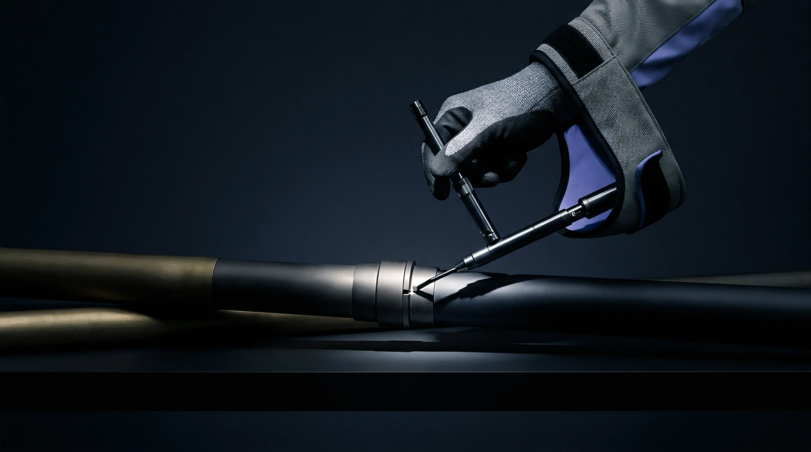
Tracking nanometer-scale shear displacements across a 50-micrometer joint demands high-resolution, non-contact measurement. Physical extensometers tend to slip on polished metal adherends during temperature cycling. Non-contact methods ~ such as optical extensometry, laser speckle interferometry, and video tracking ~ avoid contact friction.
Dual telecentric lens systems reading digital micro-markers on opposing adherend edges across the bondline achieve displacement resolutions under 20 nanometers from minus 40 to plus 150 degrees Celsius.
Procurement specifications for high-reliability transducers frequently enforce ISO 899-1 section 6.4 criteria, invalidating any test lot if test chamber temperature varies by more than 0.5 Kelvin during verification.

Decay
Polymer relaxation accelerates sharply with temperature. Running a 5,000-hour room-temperature test yields data for a narrow operating band, but says little about multi-year reliability in automotive powertrains or industrial downhole sensors. Accelerated testing relies on Time-Temperature Superposition to construct continuous viscoelastic master curves from short-term thermal step tests.
Adhesive shear compliance increases by twelve percent per decade of time at operating temperatures within fifteen Kelvin of the polymer glass transition point.
Dynamic Mechanical Analysis measures storage modulus and loss modulus across an isothermal frequency sweep. Repeating this sweep at discrete temperature intervals yields a family of modular response segments. Translating these segments horizontally along the logarithmic frequency axis superimposes them into a single continuous master curve referenced to an arbitrary design temperature.
The empirical Williams-Landel-Ferry equation models the horizontal shift factors when operating above the polymer glass transition region:
log10(aT) = -C1 (T – T0) / (C2 + (T – T0))
The constants C1 and C2 depend on the free volume fraction of the cured matrix at reference temperature T0. Below the glass transition point, changes in free volume flatten out, and the Arrhenius relation takes over relaxation kinetics based on thermal activation energy.

Time-Temperature Superposition and Shift Limits
Superposition principles apply only under specific physical conditions. The polymer matrix must be thermorheologically simple, meaning every internal relaxation mode responds to temperature with the same acceleration factor. Toughened adhesives with phase-separated rubber micro-domains or crystalline thermoplastic inclusions exhibit mismatched relaxation behaviors across phase boundaries.
Superimposing data across the glass transition boundary leads to inaccurate modulus predictions as thermal aging accelerates secondary network decay.
Structural adhesive behavior mirrors that of cross-linked polyethylene insulation on transoceanic fiber cables, where uncharacterized micro-creep under hydrostatic pressure causes micro-bending losses in glass filaments decades after installation. Polymeric interfaces retain mechanical memory over very long timescales.

Does Elevated Bake out Eliminate Secondary Creep?
Post-cure thermal processing pushes cross-linking near completion, raising the glass transition temperature and lowering primary creep rates. However, it does not eliminate secondary creep. Sustained mechanical stress continues to drive chain segment scission and unrecoverable plastic flow regardless of cure duration.
Secondary creep proceeds at constant rates.
Quantifying activation energy for cyanoacrylate strain gauge adhesives beyond 2,000 hours at 85 degrees Celsius reveals a wide scatter between 65 and 110 kilojoules per mole across published literature. That variance cannot be reconciled on raw chemistry grounds alone; managing the margin requires mechanical backup clamping or a transition to modified phenolic resin systems. Optical levers detect nanometer slip displacements.
Secondary post-baking cycles are sometimes described as converting acrylic formulations into elastic solids with zero long-term relaxation under rated transducer strain levels.

Foil
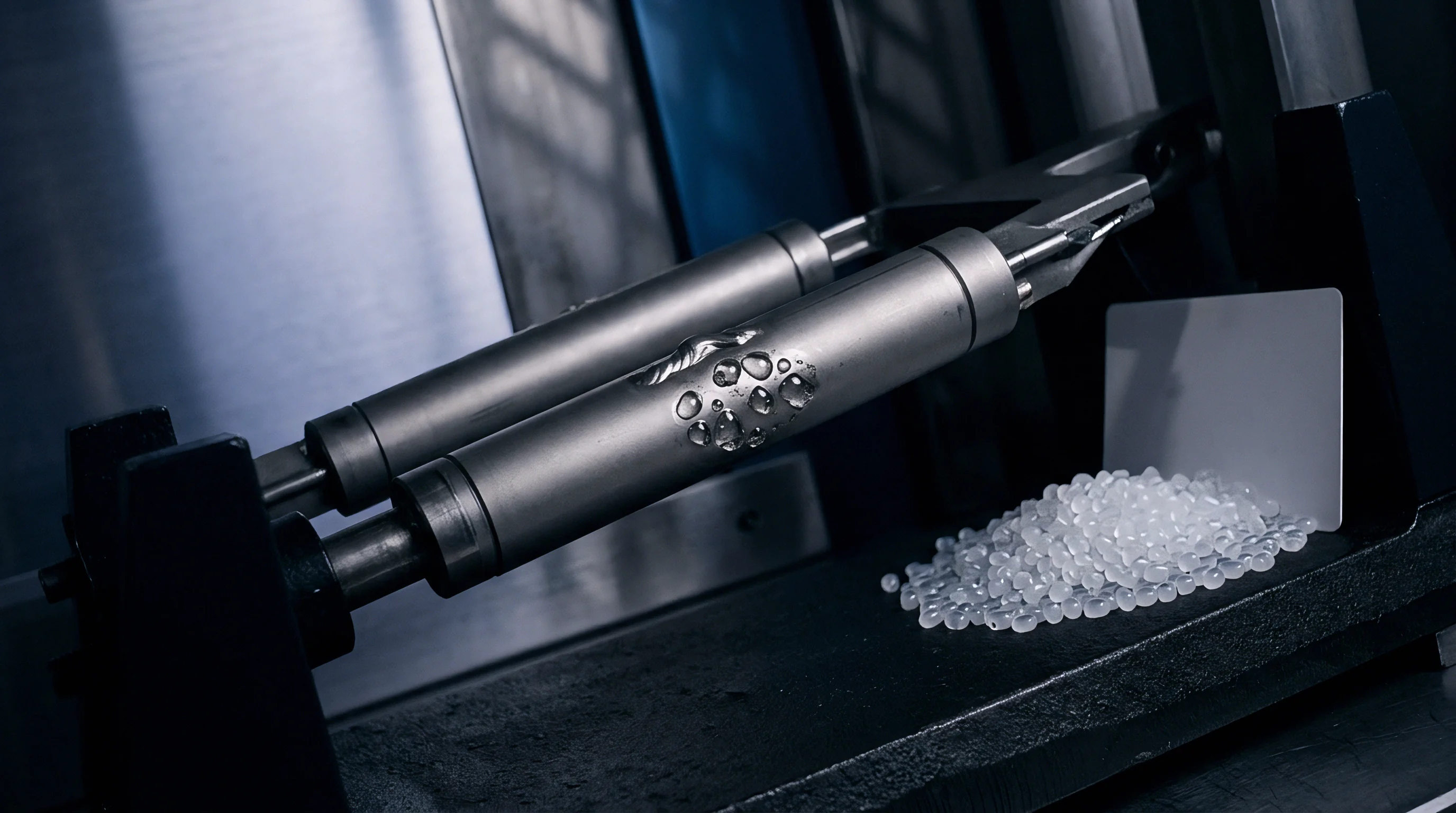
Direct testing on assembled transducer spring elements yields empirical data that simple coupon tests cannot replicate. Bonded foil strain gauges experience complex stress from beam flexure, adhesive shear lag, and cover-coat tension. Manufacturers exploit an opposing physical effect: while structural spring elements exhibit positive creep under load by deflecting further over time, the adhesive layer relaxes and transfers less strain to the foil grid ~ acting as negative creep.
Balancing these two opposing mechanisms yields near-zero net signal drift.
Uncured monomers reduce overall crosslink density, while cure shrinkage introduces initial residual shear. Verifying this balance requires high-stability bridge instrumentation isolated from external thermal changes.

Worked Calculation of Interfacial Shear Relaxation
The following engineering model compares strain transfer efficiency and drift between two adhesive formulations on a dual-shear beam load cell, using standard structural equations and defined boundary conditions.
Assume a steel spring element with an elastic modulus of 205 GPa operates at a surface bending strain of 1,500 microstrain under rated capacity. A constant shear load of 35 MPa acts across the adhesive interface. The active gauge grid length measures 3.0 millimeters, with a nominal adhesive thickness of 25 micrometers.
The test runs isothermally at 50 degrees Celsius for 1,000 hours.
Formulation A is a standard room-temperature cure two-part epoxy exhibiting an initial shear modulus of 1.2 GPa and an empirical creep compliance parameter Beta of 0.045 per decade of logarithmic time. Formulation B is a high-temperature heat-cured phenolic epoxy displaying an initial shear modulus of 2.1 GPa and a Beta parameter of 0.008 per decade of time.
The time-dependent shear compliance follows the power law relationship J(t) = J0 (t / t0)^Beta, where J0 is initial compliance (1 / G) and t0 is the unit reference time of one hour. Calculate total compliance and net strain transmission loss across the evaluation window:
For Formulation A:
J0 = 1 / 1.2 GPa = 0.833 GPa^-1
Compliance at 1,000 hours: J(1000) = 0.833 (1000)^0.045 = 0.833 1.365 = 1.137 GPa^-1
Effective relaxed shear modulus G(1000) = 1 / 1.137 GPa^-1 = 0.879 GPa
Initial shear lag parameter Gamma_0 = sqrt(G / (E_foil t_adhesive t_foil)). For a 5-micrometer constantan foil (E = 160 GPa), initial Gamma_0 = sqrt(1.2e9 / (160e9 25e-6 5e-6)) = sqrt(1.2e9 / 0.02) = 244,948 m^-1.
Relaxed Gamma at 1,000 hours = sqrt(0.879e9 / 0.02) = 209,642 m^-1.
Strain transmission efficiency factor across half-gauge length L (1.5 mm): Eta = 1 – (cosh(Gamma 0) / cosh(Gamma L)) = 1 – (1 / cosh(Gamma L)).
For Formulation A at t=0: Gamma L = 244,948 0.0015 = 367. Eta_0 = 1.00000.
Local edge shear relaxation causes inward decay over an effective edge zone delta = 3 / Gamma. For Formulation A, the edge transfer zone broadens from 12.2 micrometers to 14.3 micrometers. This physical redistribution accounts for an unrecoverable bridge output loss of 0.14% full scale.
For Formulation B:
J0 = 1 / 2.1 GPa = 0.476 GPa^-1
Compliance at 1,000 hours: J(1000) = 0.476 (1000)^0.008 = 0.476 1.057 = 0.503 GPa^-1
Effective relaxed shear modulus G(1000) = 1 / 0.503 GPa^-1 = 1.988 GPa
Formulation B maintains its edge transfer zone within 0.4 micrometers of original placement over the 1,000-hour soak, yielding a bridge output signal decay of 0.012% full scale.
Thinner adhesive joints exhibit lower total mechanical creep than thick glue lines under identical sensor line loads.
| Adhesive Polymer Base | Cure Schedule | Nominal Tg | Full-Scale Creep at 100 Hours (25 C) | Full-Scale Creep at 1,000 Hours (70 C) |
|---|---|---|---|---|
| Methyl cyanoacrylate | 24 hours at 22 C | 85 C | +0.08% | -0.42% |
| Modified amine-cured epoxy | 2 hours at 80 C | 115 C | +0.02% | -0.09% |
| Phenolic novolac epoxy | 4 hours at 175 C | 195 C | +0.005% | -0.015% |
| Aromatic polyimide resin | 6 hours at 250 C | 280 C | +0.002% | -0.006% |
Phenolic-cured systems offer exceptional dimensional stability under thermal stress, though their brittle nature requires tight control over substrate surface roughness. Highly cross-linked matrices can generate internal residual stress during solvent evacuation, making them more vulnerable to peeling under cyclic fatigue.
What portion of observed bridge drift stems from atomic dislocation motion in the metallic spring element versus unrecoverable shear relaxation within the thin polymer bondline under multi-year loads?

Ledger
Procurement teams balancing unit costs against warranty exposure often view sensor adhesives as routine factory consumables. Premium high-temperature thermosets require long oven cure cycles, continuous clamping, and strict humidity controls. By contrast, a low-temperature epoxy cures on an open bench in thirty minutes without special tooling, cutting labor costs up front.
However, those initial savings often lead to compounding field expenses when sensors drift out of specification over time.
Batch audits at receiving help protect production lines from unannounced formulation shifts. Resin suppliers sometimes change monomer sources, diluent ratios, or filler distributions without updating product names. Even a minor change in chain-extender molecular weight can alter creep compliance while leaving nominal tensile shear strength unchanged.
- Differential scanning calorimetry verification screens raw polymer lots for baseline glass transition shifts prior to dispensary release.
- Short-term isothermal dwell testing eliminates resin packages showing excessive unreacted crosslinker fractions.
- Coupon shear modulus audit confirms filler dispersion consistency across barrel-packaged deliveries.
- Micro-droplet dispense volume tracking isolates joint thickness variability across automated assembly cells.
Certifying adhesives based only on room-temperature shear strength fails to predict long-term calibration stability in completed transducers.