Piezoresistive Pressure Sensor Zero Drift under Variable Atmospheric Humidity
Dynamic atmospheric humidity alters gel swelling stress and dielectric passivation properties in piezoresistive sensors, driving measurable zero baseline drift.


Diffusion
Atmospheric water vapor penetrates non-hermetic sensor packaging through organic sealants and exposed interfacial boundaries. In piezoresistive pressure sensors, the micromachined silicon die contains Wheatstone bridge resistor networks created through ion implantation or boron diffusion. When ambient humidity fluctuates, water vapor diffuses across the protective encapsulants, reaching the silicon substrate and passivation layers.
As moisture accumulates, it alters the physical stress state of the die and disrupts the bridge’s electrical equilibrium, causing an uncommanded shift in the zero-pressure output signal.
This baseline instability stems from coupled mechanical and electrical mechanisms. Water molecules migrating through protective polymers exert swelling pressure directly against the microscopic silicon diaphragm. At the same time, polar water molecules that condense on or absorb into thin-film silicon dioxide or silicon nitride passivation layers alter surface dielectric properties, introducing parasitic conductive pathways and shifting carrier concentrations in the piezoresistive regions.
Tracing this drift requires looking closely at how moisture moves from the surrounding air to the active elements on the die.

Moisture Ingress Mechanics in Piezoresistive Dies
Water molecules migrate through silicone gel matrices toward the underlying sensor structure, driven by atmospheric humidity at the package boundary. Under steady-state conditions, moisture diffusion through the bulk polymer follows Fickian kinetics, where vapor flux depends on the diffusion coefficient of the encapsulant and the concentration gradient across the package volume. Silicon oxide absorbs this ambient vapor, and as moisture levels rise outside the housing, the resulting vapor pressure gradient forces water molecules through the molecular voids of the gel.
Once at the die surface, water molecules interact directly with the passivation coating protecting the integrated Wheatstone bridge. Standard MEMS packaging relies on thin films of plasma-enhanced chemical vapor deposition silicon nitride or thermal silicon dioxide to isolate active boron-doped silicon traces from environmental contamination. Yet these thin films still absorb moisture through micro-porosity, grain boundaries, and pinhole defects.
As water collects within the passivation layer, lattice hydration induces localized compressive stress, shifting the piezoresistive coefficient of the underlying silicon through coupled stress-optic and piezoresistive effects.
| Package Configuration | Passivation Layer Type | Diffusion Time Constant (Hours) | Zero Drift Rate (%FS / %RH) | Recovery Time (Hours) |
|---|---|---|---|---|
| Open Cavity with Dimethyl Silicone Gel | Thermal Silicon Dioxide (100 nm) | 4.2 | 0.018 | 14.5 |
| Open Cavity with Fluorosilicone Gel | PECVD Silicon Nitride (300 nm) | 18.6 | 0.004 | 38.0 |
| Glob-Top Epoxy Potting | Dual Layer SiO2/Si3N4 | 72.0 | 0.009 | 120.0 |
| Hermetic TO-8 Header with Glass Seal | Passivated Silicon Die | Infinite | 0.000 | 0.0 |
In unpassivated silicon bridge configurations, the magnitude of humidity-induced zero drift scales directly with the concentration of polar molecules present at the silicon-passivation interface. Lowering ambient humidity removes surface-bound water slowly because of desorption hysteresis, producing a delayed recovery trajectory that complicates static zero-point calibration routines.
Moisture absorption into silicon passivation coatings alters internal stress states and introduces baseline output errors without changes in applied mechanical pressure.

Dielectric Charge Accumulation and Parasitic Paths
Absorbed water molecules form polarized dipoles along the passivation layer covering active resistor traces. Liquid water has a high dielectric constant ~ approximately 80 at room temperature ~ compared to dry silicon dioxide, which ranges between 3.9 and 4.2. As moisture accumulates over the Wheatstone bridge legs, the local permittivity increases sharply, altering surface potential distributions across the p-n junctions that isolate boron-doped piezoresistors from the n-type silicon substrate.
Under operational bias voltages, surface charge accumulation induces an inversion layer in the lightly doped silicon regions adjacent to the piezoresistors, shifting the bridge offset. This field-effect modulation changes the effective cross-sectional area of the conductive piezoresistive channel and alters its nominal resistance. Because moisture accumulates non-uniformly across the layout of the four bridge resistors, the legs experience unequal resistance changes, unbalancing the bridge and producing a net zero output drift.
Capillary action transports vapor rapidly through micro-voids, creating parasitic leakage paths parallel to the high-impedance Wheatstone bridge resistors. When liquid water reacts with ionic contaminants ~ such as residual sodium or chloride ions left from wafer fabrication ~ it forms conductive electrolyte traces across the die surface. Even sub-nanoampere leakage currents across the passivation layer alter voltage division at the bridge nodes, driving zero drift above 0.5% of full-scale output at relative humidities over 80% RH.
Isolating these parasitic electrical effects from mechanical swelling forces during multi-week exposure trials remains a central challenge for metrologists.


Gel
Siloxane polymers serve as flexible potting compounds that shield delicate bond wires from mechanical shock. Piezoresistive pressure sensors designed for harsh environments frequently fill the sensor cavity with soft silicone gels, which transmit applied fluid pressure directly to the micromachined silicon diaphragm while isolating internal electrical interconnects. However, organic silicone gels readily absorb atmospheric moisture.
The resulting volumetric expansion generates parasitic mechanical forces across the underlying sensor die.
Absorbed water vapor interacts with the siloxane matrix through hygro-mechanical coupling. As ambient relative humidity rises, water molecules occupy free volume sites within the cross-linked gel matrix until reaching equilibrium with the surrounding vapor pressure. This accumulation forces siloxane polymer chains apart and causes measurable swelling.
When confined within a rigid sensor housing, that expansion converts directly into compressive and shear stresses across the silicon diaphragm.

Hygro Mechanical Strain Generation
Polymeric potting media absorb moisture from ambient air until chemical potential equilibrium is reached. The material’s volumetric swell coefficient dictates how much mechanical force is transferred to the silicon diaphragm as the gel expands and deforms the bridge. Because the piezoresistive effect in silicon is highly sensitive to anisotropic stress, even micro-strain level deformations produce measurable changes in output voltage.
The orientation of swelling forces relative to the silicon die’s crystalline axes dictates both the direction and magnitude of the resulting zero drift. Piezoresistors implanted along target crystallographic directions convert in-plane principal stresses and out-of-plane shear stresses into resistance changes. When expanding silicone gel presses against the diaphragm, it creates an asymmetric pressure profile across the micromachined surface.
Constrained by the rigid substrate frame, the diaphragm edges experience high stress concentrations, while the center deflects upward or downward depending on gel height and housing boundaries.
- Hygroscopic volumetric expansion generates compressive stress profiles across the silicon diaphragm surface as moisture concentration rises inside the package volume.
- Interfacial shear stress generation damages microscopic bond wire joints at the gel-substrate interface during rapid humidity swings.
- Asymmetric gel meniscus profile induces unbalanced force vectors across opposing legs of the Wheatstone bridge, adding to baseline zero offset errors.
- Temperature dependent moisture solubility creates coupled hygro-thermal zero drift vectors that diverge significantly from dry thermal compensation models.

Polymer Swelling Coefficients across Temperature Gradients
Volumetric expansion in organic potting matrices depends heavily on temperature and glass transition boundaries. While fluorosilicone limits vapor expansion, standard dimethyl silicone gels show an increase in moisture solubility at higher temperatures, which exacerbates swelling stresses. High relative humidity combined with elevated operating temperatures accelerates both moisture diffusion rates and the final equilibrium swelling force exerted on the pressure die.
| Material Designation | Density (g/cm³) | Moisture Absorption at 85% RH (%) | Volumetric Swelling Coefficient (1/ %RH) | Young’s Modulus (MPa) |
|---|---|---|---|---|
| Standard Dimethyl Silicone Gel | 0.97 | 0.15 | 1.2 × 10⁻⁴ | 0.05 |
| High-Purity Fluorosilicone Gel | 1.25 | 0.03 | 2.8 × 10⁻⁵ | 0.12 |
| Soft Epoxy Potting Compound | 1.15 | 0.45 | 5.5 × 10⁻⁴ | 150.00 |
| Polyurethane Gel Encapsulant | 1.08 | 0.80 | 9.1 × 10⁻⁴ | 2.50 |
The encapsulant’s mechanical modulus dictates how effectively stress transfers from swollen gel to the silicon structure. Soft gels with a low Young’s modulus deform internally, absorbing much of the swelling energy and easing stress on the diaphragm. Stiffer gels ~ or aged polymers that have undergone post-cure cross-linking ~ transmit those swelling forces directly to the die surface.
Over time, exposure to ultraviolet radiation, thermal cycling, and continuous moisture degrades the polymer, increasing gel modulus and magnifying humidity-driven zero offset drift.
Standard thermal compensation routines fail to correct zero drift when moisture swelling alters gel modulus and induces non-linear strain profiles across piezoresistive bridge elements.
Ignoring hygro-mechanical swelling during sensor selection can introduce serious operational errors in field applications. Uncompensated gel swelling causes pressure sensors to output false baseline shifts that look like real pressure changes, triggering unnecessary shutdowns, distorting flow calculations, and forcing costly service calls.

Hysteresis
Environmental testing reveals distinct offset pathways when relative humidity cycles between low and high vapor concentrations. Piezoresistive pressure sensors exposed to dynamic humidity transitions rarely respond symmetrically. As ambient humidity climbs from a dry baseline to high moisture levels and returns to dry conditions, the zero-pressure output voltage traces a distinct hysteresis loop.
This non-reversible behavior complicates recalibration and degrades accuracy specifications over time.
Humidity hysteresis stems primarily from differing kinetic rates between water absorption and desorption inside organic materials. Water diffuses into silicone gels and dielectric thin films rapidly under steep vapor pressure gradients. Desorption, however, requires water molecules to break hydrogen bonds with surface hydroxyl groups on silicon oxide and diffuse outward through polymer chains against diminishing concentration gradients ~ a kinetic asymmetry that leaves a long recovery lag during drying cycles.

Relative Humidity Step Testing Protocols
Characterizing humidity hysteresis requires precise environmental control inside test chambers. Test sequences hold ambient temperature strictly constant, typically at 25°C or 40°C, while stepping relative humidity from 10% to 90% RH in increments like 15% RH. At each plateau, the sensor remains exposed for more than five times the diffusion time constant of its encapsulant, ensuring moisture saturation reaches equilibrium before recording zero-pressure output voltages.
On the descending leg of the humidity cycle, output voltages systematically deviate from the values recorded at identical setpoints during the ascending leg. The maximum difference between these ascending and descending offset values defines the peak humidity hysteresis error, expressed as a percentage of full-scale span (%FS). Left uncompensated, this drift can easily trigger false system alarms.
- Stabilize the device under test inside the environmental chamber at 25°C and 10% relative humidity for 24 hours to establish a dry baseline.
- Increase chamber relative humidity from 10% to 85% RH in 15% RH steps, holding each step for 8 hours while continuously logging zero-pressure differential output voltage.
- Hold the maximum humidity plateau at 85% RH for 48 hours to induce complete moisture saturation across internal gel and passivation interfaces.
- Decrease chamber relative humidity back to 10% RH in identical 15% RH steps, holding each step for 8 hours to capture the desorption trajectory.
- Calculate peak humidity hysteresis from the maximum voltage divergence between ascending and descending steps at equivalent relative humidity plateaus.

Which Relative Humidity Ramp Rates Expose Irreversible Shift?
Rapid humidity transitions induce transient thermal and mechanical gradients across silicon substrates. Exposing a sensor to fast humidity steps ~ such as cycling from 20% to 90% RH in under five minutes ~ triggers localized latent heat effects. Because moisture absorption into silicone gel is exothermic, it releases small amounts of heat that alter die temperature, while rapid desorption causes evaporative cooling.
These brief thermal spikes generate transient zero drift that can mask underlying hygro-mechanical and dielectric behavior.
When humidity ramps faster than water can diffuse through the gel, steep concentration gradients develop across the encapsulant volume. The outer gel layer swells rapidly while the deeper material at the die interface stays dry. This differential swelling creates bending moments across the silicon substrate, causing zero offset spikes that persist until moisture equilibrates throughout the polymer volume.
Running slow step tests prevents these transient gradients from skewing static hysteresis measurements.
| Uncertainty Component | Standard Uncertainty (mV) | Probability Distribution | Sensitivity Coefficient | Uncertainty Contribution (mV) |
|---|---|---|---|---|
| Chamber RH Fluctuation (±1.5% RH) | 0.087 | Normal | 0.042 mV/%RH | 0.0037 |
| Chamber Temperature Drift (±0.1°C) | 0.058 | Rectangular | 0.120 mV/°C | 0.0070 |
| Bridge Excitation Voltage Drift (±0.01V) | 0.006 | Normal | 1.000 mV/V | 0.0060 |
| Data Acquisition Voltage Resolution | 0.002 | Rectangular | 1.000 | 0.0020 |
| Hygro-Mechanical Gel Hysteresis (Observed) | 0.245 | Normal | 1.000 | 0.2450 |
| Combined Standard Uncertainty (u_c) | – | Normal | – | 0.2452 |
| Expanded Uncertainty (U, k=2) | – | Normal (95% Coverage) | – | 0.4904 |
Test chamber trials show a non-linear zero drift trajectory during prolonged high-humidity holds. In the expanded uncertainty calculation for RH exposure tests using the budget structure above, intrinsic gel hysteresis dominates the total uncertainty budget, accounting for over 99% of the combined variance. Environmental chamber stability and measurement noise remain negligible factors compared to the physical instability of the saturated encapsulant.
Long-term exposure to relative humidity levels above 85% RH can cause permanent shifts in baseline output. Moisture lingering at the silicon-gel interface promotes microscopic oxidation on exposed metal traces and accelerates stress relaxation in die-attach adhesives. Once these structural shifts happen, returning the sensor to 10% RH will not restore the original baseline voltage, leaving a permanent zero offset drift that field calibration cannot distinguish from mechanical diaphragm fatigue.
Determining test duration requires balancing characterization depth against manufacturing throughput. Screening every production unit through multi-day humidity cycles creates severe factory bottlenecks and drives up test costs.
- Equilibrium stabilization threshold sets mandatory hold times at each humidity plateau based on package diffusion geometry.
- Permeation barrier thickness dictates how long water vapor takes to reach saturation at the die interface.
- Desorption latency factor determines the drying time required to verify zero recovery before final packaging.
- Max ambient ramp rate limit prevents heat-of-adsorption thermal transients from distorting static humidity hysteresis data.
A 24-hour humidity step test conducted at 85% relative humidity provides a reliable indicator of long-term zero drift susceptibility in organic-encapsulated pressure transducers.
Silicon dioxide passivation isolates active traces from environmental moisture, but gel-potted piezoresistive pressure sensors still experience baseline drift under varying atmospheric conditions.

Isolation
Protecting sensitive silicon piezoresistors from ambient moisture demands robust mechanical barriers between the sensing element and external air. Media isolation techniques shield the micromachined silicon die from corrosive gases and moisture vapor while preserving the compliance needed to transmit pressure accurately. Choosing an isolation architecture involves balancing baseline zero drift performance against component cost, package size, and dynamic pressure response.
While basic silicone gel encapsulation provides low-cost protection against splash water, it cannot block water vapor transport over long operational lifespans. Applications exposed to continuous high humidity, condensing conditions, or outdoor weather require more robust isolation strategies ~ ranging from specialized hydrophobic barriers to hermetically sealed, oil-filled stainless steel diaphragm assemblies.

Oil Filled Stainless Steel Diaphragm Barriers
In oil-filled, media-isolated piezoresistive sensors, a thin corrugated metallic diaphragm ~ typically fabricated from 316L stainless steel, Hastelloy, or Tantalum ~ interfaces directly with the process medium. Vacuum-distilled silicone or fluorocarbon oil fills the sealed cavity surrounding the unpassivated silicon pressure die. Applied pressure deflects the external metallic diaphragm, which transfers fluid pressure through the oil fill to the internal silicon diaphragm.
This design eliminates water vapor contact with the silicon die entirely. Hermetic glass-to-metal feedthroughs seal electrical leads exiting the steel housing, preventing humidity ingress along wire paths. Because water vapor cannot penetrate the welded metallic enclosure or glass seals, oil-filled isolated sensors show zero measurable humidity-induced zero drift even under continuous 100% RH exposure.
While fluorosilicone limits vapor expansion in gel designs, hermetic seals eliminate moisture transport altogether.
| Isolation Architecture | Vapor Ingress Resistance | Zero Drift Rate (%FS / Year at 85% RH) | Thermal Sensitivity Coefficient (%FS/°C) | Relative Unit Cost Factor |
|---|---|---|---|---|
| Direct Die Gel Potting (Dimethyl) | Low | 0.850 | 0.012 | 1.0x |
| Fluorosilicone Gel Potting | Moderate | 0.220 | 0.018 | 1.4x |
| Parylene C Conformal Coating + Gel | High | 0.080 | 0.015 | 2.1x |
| Oil-Filled 316L Stainless Diaphragm | Complete (Hermetic) | 0.000 | 0.045 | 4.8x |
| Glass-Passivated Ceramic Cell | High | 0.025 | 0.020 | 3.2x |
Oil-filled assemblies introduce thermal expansion trade-offs despite offering complete moisture protection. The internal oil volume expands and contracts with ambient temperature swings, exerting thermal pressure on the die and producing a higher thermal zero coefficient than bare silicon. Mitigating this effect requires keeping oil volume to a strict minimum and incorporating secondary thermal compensation electronics within the assembly.

Vented Gauge Reference Tube Desiccant Systems
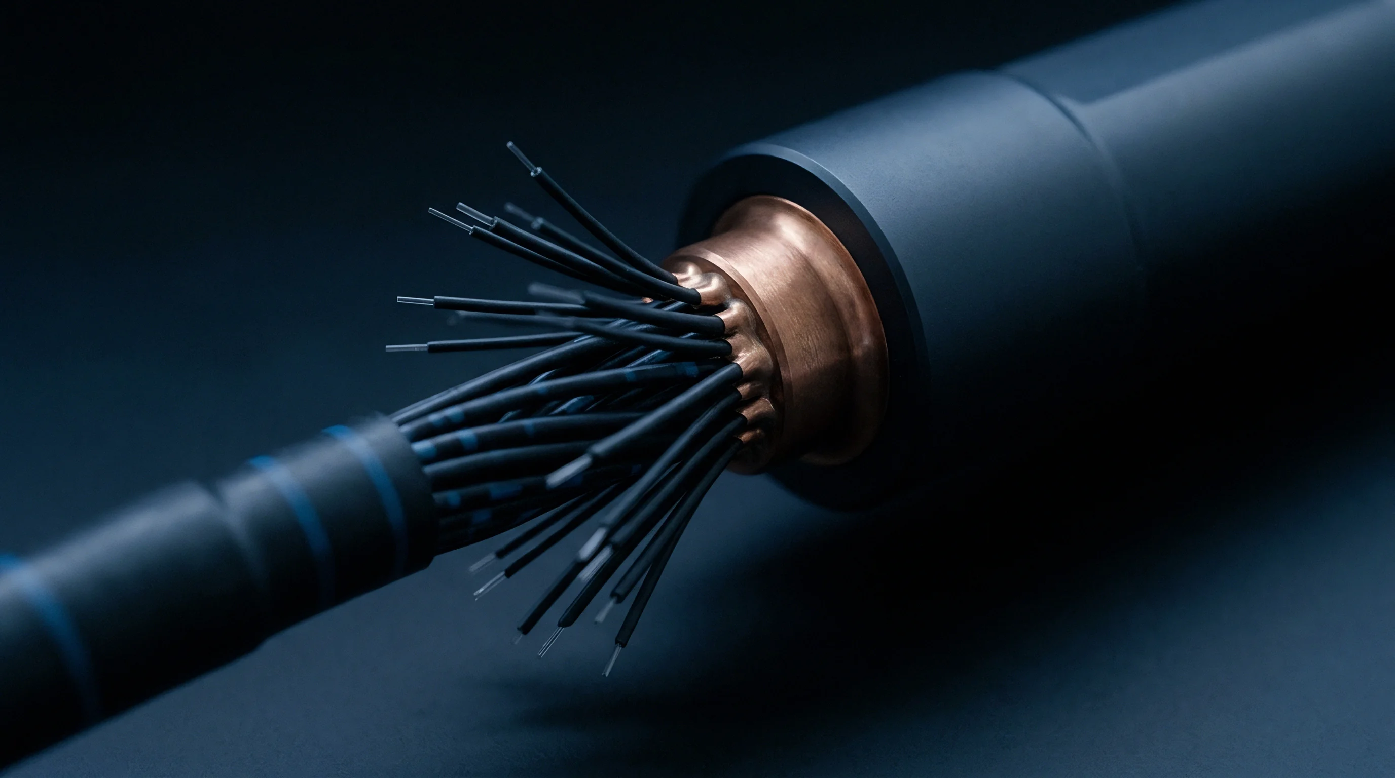
Gauge pressure transducers reference atmospheric pressure through internal vent pathways exposed to ambient humidity. These sensors use a small flexible tube within the cable bundle to route atmospheric pressure to the back surface of the silicon diaphragm, preventing ambient barometric changes from distorting readings. However, moist air traveling down the vent tube enters the rear cavity of the sensor housing directly.
Condensation forming inside this reference cavity causes severe zero offset shifts and corrodes exposed backside metal traces. When sensor housing temperatures drop below the ambient dew point, vapor entering through the vent tube condenses. Because desiccant packs saturate over time, vented gauge installations frequently use inline desiccant filters or hydrophobic ePTFE (expanded polytetrafluoroethylene) vent membranes.
These hydrophobic membranes let air molecules pass freely while blocking liquid water droplets and resisting vapor transport, preventing internal condensation in humid environments.
- Hydrophobic membrane pore sizing dictates liquid water entry pressure while maintaining open atmospheric venting.
- Inline desiccant canister capacity limits service intervals before media color changes indicate moisture saturation.
- Flexible vent tube inner diameter prevents capillary condensation lock that can restrict atmospheric pressure equalization.
- Dual-cavity housing design isolates sensitive bridge electronics from backside atmospheric venting channels.
Choosing a media isolation system requires weighing environmental exposure criteria against lifetime costs. System integrators who specify low-cost gel-potted sensors for outdoor HVAC or water infrastructure applications often incur field maintenance costs that quickly eclipse the higher initial price of oil-filled isolated transducers.
Integrating hydrophobic ePTFE membranes into vented gauge cables reduces condensation-induced zero drift by over 90% in outdoor environmental monitoring applications.
Sourcing agreements referencing ISO 17025 accredited testing often require vendors to certify that zero-point thermal and humidity hysteresis testing covers the full operating temperature range, backed by contractual remedies if long-term field drift exceeds specified limits.


Correction
Digital signal conditioning electronics mitigate baseline offset wander caused by environmental humidity fluctuations. Advanced piezoresistive pressure sensors incorporate integrated application-specific integrated circuits (ASICs) capable of performing multi-variable mathematical correction. While traditional analog trim networks only correct static temperature errors, digital architectures measure environmental parameters alongside raw bridge signals to actively compensate for humidity-induced baseline drift in real time.
Effective correction relies on mapping the non-linear interactions between temperature, relative humidity, and zero-point offset. Embedded processors use polynomial surface-fitting models or high-resolution lookup tables in non-volatile memory to compute dynamic correction factors. By continuously monitoring ambient humidity with an internal digital sensor, the signal conditioner subtracts predicted moisture errors from the raw bridge signal before passing data to the host system.

Algorithmic Moisture Drift Compensation
Embedded microcontrollers use multi-parameter lookup tables linking relative humidity measurements to offset adjustments, resetting the zero reference during recalibration. The compensation algorithm processes inputs from both the primary piezoresistive bridge and an auxiliary relative humidity sensor co-located in the housing, using dual-parameter polynomial equations to model combined thermal and hygric drift responses.
Zero offset correction typically uses a second-order surface model where the corrected zero output voltage equals raw output minus a function of temperature and relative humidity. System calibration requires logging zero-pressure bridge outputs across an environmental test matrix ~ for instance, three temperatures combined with three relative humidity levels ~ yielding nine data points to calculate compensation matrix coefficients.
Because vapor pressure shifts the zero baseline, active internal heating offers a physical alternative to algorithmic correction. Integrating a micro-heater onto the silicon or ceramic substrate carrier allows control electronics to keep die temperature slightly above the ambient dew point, preventing local relative humidity inside the package from reaching critical absorption thresholds. Keeping internal relative humidity below 30% RH virtually eliminates hygro-mechanical gel swelling and surface dielectric polarization drift.

Commercial Recalibration Schedules and Operational Costs
Managing long-term accuracy in humid environments involves balancing field servicing frequency against total ownership expense. Piezoresistive pressure sensors operating under high humidity experience cumulative zero-point drift over time, so field calibration protocols must account for seasonal humidity changes to keep false measurements from triggering control errors.
Field returns show cases where humidity-induced zero drift exceeded initial tolerance specifications within twelve months of deployment. Sensors in high-humidity tropical processing facilities required zero-point recalibration every six months to maintain a 0.25% FS accuracy window, whereas identical sensors operating in climate-controlled indoor environments stayed compliant across 24-month intervals. Establishing an effective recalibration schedule requires measuring field drift velocity in real operating environments rather than relying on dry laboratory specs.
Building robust calibration dossiers requires thorough documentation of environmental conditioning prior to baseline verification. Technical packages must detail pre-conditioning bake-out parameters, relative humidity step rates, and expanded uncertainty calculations to pass accredited quality audits.
- Pre-test thermal bakeout removes accumulated moisture from internal gel matrices before establishing the zero reference.
- Multi-point environmental matrix profiling records zero offset voltages across combined temperature and relative humidity plateaus.
- Expanded uncertainty budget documentation specifies coverage factors and reference standard traceability chains for field verification.
- Recalibration frequency guidelines establishes operational service intervals based on site-specific humidity exposure.
A practical rule of thumb is that pressure sensors exposed to continuous relative humidity above 80% RH require zero-point verification intervals half as long as those deployed in dry environments.