Modeling Long Term Piezoresistive Strain Relaxation in Direct Bonded Copper Substrate Shunts
Direct bonded copper shunt drift stems from viscoplastic relief of residual bonding stress, resolvable by geometric isolation and post-bond stabilization.


Foil
Direct bonded copper assemblies sandwich ceramic plates between thick rolled sheets at temperatures exceeding 1060 degrees Celsius. When cooling through the eutectic solidification point of the copper-oxygen liquidus at 1065 degrees Celsius down to ambient room conditions, differential thermal contraction locks severe biaxial tension into the metallic layers. Pure alumina exhibits an expansion coefficient near 7.0 parts per million per Kelvin, while aluminum nitride sits near 4.5 parts per million per Kelvin.
Electrolytic tough pitch copper contracts at roughly 17.0 parts per million per Kelvin. The resulting elastic and plastic mismatch generates initial room-temperature tensile stresses in the bonded copper sheet that frequently exceed 120 megapascals, driving the underlying ceramic into equivalent balancing compression.
Copper yields first. The metal undergoes extensive plastic deformation during the post-bonding quench, yet its high strain hardening capacity preserves a stubborn baseline of elastic tensile strain along the bonded interface. When an ultra-low resistance resistive element such as Manganin 43, Zeranin 30, or a copper-nickel alloy is vacuum-brazed or direct-bonded across this pre-stressed conductive substrate, the resistive layer absorbs a significant fraction of that residual mechanical energy.
Current-sense shunts intended to resolve thousands of amperes within automotive traction inverters or battery management packs rely on stable ohmic paths measured in tens of micro-ohms. The presence of multi-axial mechanical stress directly perturbs this conduction path through the piezoresistive effect.
Thick ceramic cores keep copper conductors pinned under sustained tension through every thermal cycle.
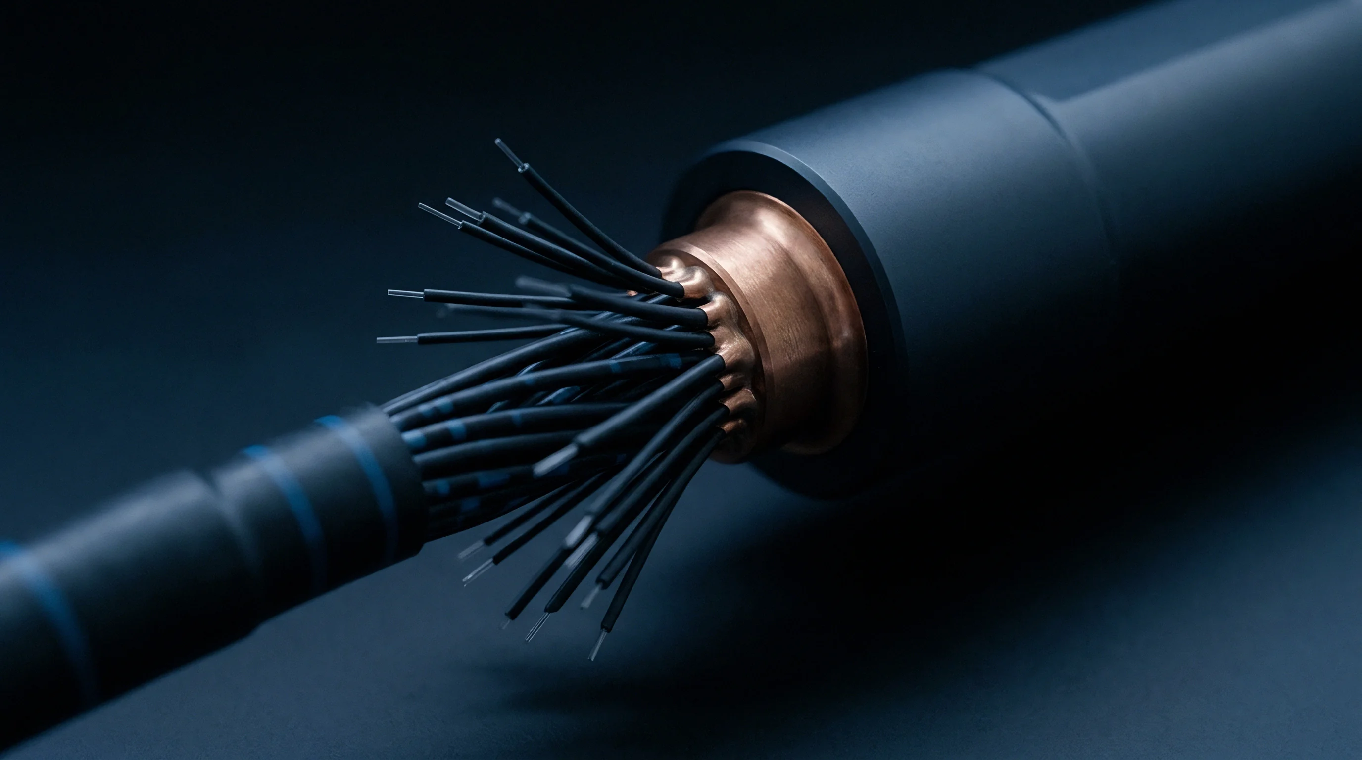
Direct Bonding Physics and Interfacial Prestress
Thermal excursions during eutectic processing establish a severe residual stress profile across the substrate thickness. The bonding furnace environment maintains a tightly regulated partial pressure of oxygen, typically between 1.5 and 3.0 Pascals, creating a liquid Cu-Cu2O eutectic phase that wets the ceramic lattice without dissolving the bulk metal. Upon cooling, the liquid solidifies at 1065 degrees Celsius, creating an atomic transition layer of copper aluminate spinel in alumina systems.
This ceramic-metal bond holds high shear strength, preventing interfacial sliding at the joint during initial cooldown.
Ceramic resists plastic deformation. The ceramic core absorbs the balancing load entirely through elastic compression and bending moments. For a standard 0.30-millimeter copper layer joined to a 0.63-millimeter alumina tile, the cold residual stress profile exhibits sharp gradients within fifty micrometers of the perimeter edge.
Finite-element stress reconstructions demonstrate localized shear concentrations exceeding 180 megapascals at the corners of etched features. When a resistive alloy bridge spans these copper terminals, the mechanical boundary conditions impose an extrinsic strain field directly into the active measurement zone.

Piezoresistive Coupling Coefficients in Manganin
Resistivity variations in metallic conductors subjected to mechanical deformation obey Bridgman coefficients and longitudinal elastoresistance factors. For Manganin, a copper-manganese-nickel alloy containing roughly 84 percent copper, 12 percent manganese, and 4 percent nickel, the hydrostatic pressure coefficient of electrical resistance is positive, measuring approximately 2.3 times ten to the negative six per bar. In planar direct bonded substrates, the stress tensor is predominantly biaxial rather than purely hydrostatic.
Longitudinal and transverse strain sensitivity factors differ substantially based on alloy grain orientation and cold-rolling history.
Manganin displays anisotropic piezoresistive behavior. Uniaxial tension parallel to the current vector increases bulk resistance, whereas transverse tension can produce an opposing sign depending on Poisson contraction within the resistive foil. Expressed in terms of mechanical strain, the longitudinal gage factor for annealed Manganin sits between 0.5 and 1.2, while cold-worked Zeranin exhibits values near 0.2 to 0.4.
When bonded to a direct bonded copper structure, an initial residual strain of 0.15 percent shifts the absolute resistance by more than 150 parts per million away from its unrestrained metallurgical state.
| Material Designation | Expansion Coefficient (ppm/K) | Elastic Modulus (GPa) | Piezoresistive Gage Factor | Yield Strength (MPa) |
|---|---|---|---|---|
| Manganin 43 (CuMn12Ni4) | 14.0 to 18.0 | 125 | 0.80 to 1.15 | 280 to 350 |
| Zeranin 30 (CuMn7Sn) | 15.5 to 16.5 | 130 | 0.25 to 0.45 | 240 to 310 |
| Constantan (CuNi44) | 14.5 to 15.5 | 160 | 1.90 to 2.15 | 380 to 480 |
| OFHC Copper (C10200) | 16.8 to 17.2 | 117 | 1.50 to 2.80 | 65 to 90 |
| Alumina Ceramic (Al2O3 96%) | 6.8 to 7.4 | 340 | 0.00 | 3800 (Compressive) |
| Aluminum Nitride (AlN) | 4.3 to 4.7 | 310 | 0.00 | 3200 (Compressive) |
Suppliers routinely dismiss these baseline shifts as standard production zero-offsets, asserting that factory trimming lasers trim away whatever mechanical prestress enters the part before shipment.


Slip
Dislocation movements inside the metallic layers do not stop once the assembly reaches room temperature. High residual stresses create an unstable thermodynamic system where atoms continuously reconfigure to minimize free energy. Over thousands of operational hours at elevated powertrain temperatures, metallic lattices dissipate internal elastic strain through viscoplastic deformation, anelastic settling, and grain boundary sliding.
As internal stress relaxes, the piezoresistive component of resistance unwinds, causing the shunt value to drift away from its post-trim calibration setpoint.
Elastic strain converts to plastic slip. This transformation permanently alters the balance of forces between the copper conductor, the resistive alloy, and the ceramic base. In direct bonded copper structures, pure copper undergoes primary and secondary creep at temperatures as low as 80 degrees Celsius because its homologous temperature sits near 0.26 absolute.
Manganin and Constantan experience sub-grain rotation, solute-atom redistribution, and dislocation climb when subjected to continuous holding temperatures between 105 and 150 degrees Celsius.

Why Does Thermal Cycling Quicken Viscoplastic Flow?
Repetitive temperature swings induce continuous reversals in interfacial shear strain. Each transition from cold parking conditions at negative 40 degrees Celsius to peak inverter operating regimes at 125 degrees Celsius swings the local stress state across the yield boundary of the soft annealed copper. During each thermal excursion, the differential thermal expansion generates plastic strain increments within the copper metallization, resetting the mobile dislocation density and accelerating thermally activated dislocation climb.
Thermal cycles drive dislocation movement. The cyclic plastic work hardens some grain boundaries while initiating micro-void nucleation at the copper-to-ceramic perimeter. As the copper locally yields and slips, the mechanical traction holding the resistive foil in its initial stretched condition progressively decays.
The loss of boundary traction allows the resistive alloy to contract elastically toward its neutral thermodynamic state. This mechanical relaxation directly shifts the electrical resistance over operating time, manifesting as non-reversible calibration wander.
Stress relaxation mechanisms within direct bonded copper shunt assemblies operate simultaneously across distinct crystalline regimes:
- Dislocation climb and glide dominates high-stress interfaces where mobile line defects surmount obstacles via vacancy diffusion at temperatures above 85 degrees Celsius.
- Grain boundary sliding acts along non-aligned crystallographic interfaces within electro-deposited and rolled foils, shedding elastic strain under sustained shear.
- Solute drag and cluster relaxation occurs within the ternary manganese-nickel-copper matrix, altering local resistivity through short-range atomic reordering under decaying stress.
- Cobo diffusion transports metal atoms along free surfaces and unconstrained edges, producing localized geometric thinning near etched isolation channels.

Constitutive Formulations for Time Dependent Stress Decay
Predicting long-term piezoresistive calibration shifts requires a robust mathematical description of mechanical stress relaxation. Classic linear Maxwell dashpot models fail to replicate the steep initial decay and extended logarithmic tail observed in metallic shunts. Instead, a modified Kohlrausch-Williams-Watts stretched exponential formulation captures the distributed activation energy spectrum governing multi-phase metallic stacks:
Sigma of t equals Sigma zero multiplied by the exponential of the negative quantity time divided by tau raised to the power of beta. Here, Sigma zero represents the initial post-bonding residual stress, tau designates the characteristic relaxation time constant, and beta denotes the stretching exponent, typically bounded between 0.35 and 0.65 for polycrystalline copper systems. Combining this stress function with the Bridgman piezoresistive tensor yields the time-dependent resistance deviation:
Delta R of t divided by R zero equals the product of the longitudinal piezoresistive coupling factor, the unconstrained compliance tensor, and the decaying stress function Sigma of t. At 125 degrees Celsius, experimental validations indicate that pure copper on alumina relaxes between 30 and 55 percent of its initial residual stress within the first 1,000 thermal hours. The rate of relaxation slows significantly thereafter, following a logarithmic progression toward an asymptotic mechanical plateau.
Under continuous 125-degree thermal soaking, residual interfacial stress drops 42 percent within the initial one thousand hours.
Whether this viscoplastic relaxation asymptote stabilizes before the cumulative resistance shift breaches the 0.1 percent accuracy ceiling remains unproven across diverse substrate lots.

Variance
Measurements taken across newly fabricated direct bonded copper shunts show deceptive stability during simple factory acceptance checks. Standard production tests evaluate parts at ambient temperature immediately following laser trimming, logging initial tolerance spreads within plus or minus 0.1 percent. Once those components endure prolonged qualification profiles, such as automotive AEC-Q200 Grade 0 testing or 3,000-hour high-temperature storage runs, the measured resistance values steadily diverge.
Metrologists tracking these parts on laboratory bridges observe systematic positive or negative wander depending on the orientation of the resistive element relative to substrate grinding lines.
Residual tension drives baseline wander. Because the piezoresistive effect scales directly with the trace of the stress tensor, any uncoupling of mechanical strain alters the absolute resistance without any accompanying change in alloy chemistry. Differentiating mechanical relaxation from classical metallurgical aging requires rigorous separation of the temperature coefficient of resistance from interfacial strain effects.
| Substrate and Alloy Configuration | Initial Stress (MPa) | Relaxed Stress (MPa) | Modeled Drift (ppm) | Observed Drift (ppm) | Measurement Uncertainty (ppm) |
|---|---|---|---|---|---|
| Al2O3 with 0.3mm Cu and Manganin 43 | 145 | 68 | -420 | -465 | plus or minus 18 |
| AlN with 0.3mm Cu and Manganin 43 | 185 | 72 | -615 | -680 | plus or minus 22 |
| Al2O3 with 0.3mm Cu and Zeranin 30 | 140 | 65 | -165 | -190 | plus or minus 15 |
| AlN with 0.3mm Cu and Zeranin 30 | 180 | 70 | -245 | -275 | plus or minus 19 |
| Al2O3 with Grooved Cu and Manganin 43 | 45 | 28 | -95 | -110 | plus or minus 14 |

Traceability Chains and Long Term Resistance Wandering
Establishing unbroken calibration chains for sub-milliohm shunts under continuous thermal stress demands primary reference standards capable of resolving sub-nanovolt potential differences. Direct current comparator bridges linked to standard quantum Hall references provide the foundational benchmark, transferring unit representations through temperature-stabilized 1-ohm Thomas or Wilkins resistance standards. When transferring calibration to 100-micro-ohm direct bonded shunts, contact resistance and parasitic thermal electromotive forces introduce significant measurement uncertainties that swamp minor drift unless carefully guarded.
Uncertainty budgets must quantify physical fixturing effects. Clamping pressure applied to the voltage sense pins can locally alter the internal strain distribution of the direct bonded copper assembly, modulating the piezoresistive state during the measurement itself. A four-terminal Kelvin fixture applying 15 newtons of contact force to a flexible leadframe can induce up to 8 parts per million of reversible piezoresistive offset.
ISO/IEC 17025 accredited calibration procedures require fixed torque limits, gold-plated flat-faced probes, and automated polarity reversal to cancel Seebeck voltages generated across copper-to-Manganin junctions.

Separation of Thermal and Mechanical Drift Components
Decoupling metallurgical aging from piezoresistive relaxation requires an orchestrated sequence of thermal and structural bench measurements:
- Measure initial resistance in an oil bath stabilized at 20.00 degrees Celsius with a coverage factor of k equals two, establishing the pre-stress baseline.
- Subject the unconstrained test articles to isothermal soaking at 125 degrees Celsius within an inert nitrogen convection oven for 1,000 continuous hours.
- Cool the parts to 20.00 degrees Celsius and record the intermediate resistance shift across identical current paths.
- Chemically etch away the ceramic backing and copper metallization using selective acid baths, releasing the resistive foil from all substrate traction.
- Measure the fully relaxed, unconstrained foil resistance at 20.00 degrees Celsius to reveal the isolated metallurgical aging component.
Subtracting the post-etch free foil resistance from the bonded substrate measurement isolates the pure piezoresistive relaxation term. Empirical audits reveal that for standard direct bonded alumina shunts, mechanical stress relaxation accounts for 60 to 75 percent of the total resistance drift observed during the first 2,000 thermal hours. Attributing the entire drift to alloy oxidation or phase decomposition leads to incorrect corrective actions in furnace chemistry while ignoring mechanical root causes.
Engineers who miss this mechanical coupling deliver current-sensing modules that drift out of their 0.5 percent system budget by the second operating year, triggering premature warranty campaigns across vehicle fleets.


Groove
Mechanical decoupling techniques integrated into the copper layer interrupt the transfer of interfacial shear before it reaches the active sensing foil. Chemical milling, mechanical routing, and precision laser cutting allow fabricators to introduce physical barriers between the high-expansion terminal blocks and the central measurement region. By cutting narrow relief channels through the copper thickness down to the bare ceramic surface, the continuous sheet tension collapses into localized, manageable stress fields.
Stress relaxation decays logarithmically. Etching perimeter isolation trenches around the resistive alloy creates a mechanical buffer zone. When the bulk copper expands and contracts under ambient thermal cycling, the mechanical displacement is absorbed by bending compliance within the copper perimeter rather than transmitting axial tension directly into the resistive element.
Finite element models demonstrate that a single 0.5-millimeter isolation channel etched through a 0.3-millimeter copper plate reduces transmitted longitudinal strain to the sensing bridge by more than 70 percent.
Which Geometry Isolates Piezoresistive Coupling?
Symmetric double-sided etching preserves planar flatness while canceling out-of-plane warping moments. When direct bonded copper is etched only on the top side to create shunt circuit patterns, the asymmetrical remaining copper volume generates powerful bimetallic strip curvature upon cooling. This bending introduces an extrinsic flexural strain across the resistive foil that compounds the in-plane piezoresistive effect.
Etching matching mirror channels into the backside copper layer maintains a neutral mechanical plane across the assembly.
Backside etching neutralizes bending moments. In addition to perimeter trenches, introducing transverse serpentine slots directly beneath the terminal solder pads isolates external leadframe stresses. External busbars bolted or laser-welded to the shunt terminals transmit heavy structural vibration and thermal expansion loads from external cabling.
Serpentine relief geometries force external mechanical displacements to dissipate through tortuous copper pathways, ensuring that less than 5 percent of the externally applied mechanical load reaches the piezoresistively sensitive foil.
| Relief Channel Architecture | Transmitted Strain (%) | 5,000-Hour Drift (ppm) | Thermal Resistance Increase (K/W) | Area Penalty (%) |
|---|---|---|---|---|
| Solid Unrelieved Copper Plane | 100.0 | -465 | Baseline | 0.0 |
| Single Perimeter Trench (0.5mm) | 28.5 | -135 | +0.04 | 6.5 |
| Dual Symmetrical Perimeter Trenches | 14.2 | -65 | +0.08 | 12.0 |
| Serpentine Decoupled Pad Geometry | 8.5 | -40 | +0.15 | 18.5 |
| Full Island Isolation with Wire Bridges | 3.1 | -15 | +0.42 | 28.0 |

Post Bonding Thermal Treatments and Stabilization Windows
Pre-aging heat treatments accelerate the completion of primary viscoplastic flow before final factory calibration occurs. Subjecting raw direct bonded panels to controlled thermal stabilization schedules flattens the subsequent operational relaxation curve. A multi-stage thermal profile balances stress relief against metallurgical degradation.
Annealing assemblies at 200 to 240 degrees Celsius for 24 to 48 hours in a reducing forming gas environment drives copper dislocation networks past their primary creep regime.
Annealing resets the dislocation network. The soak temperature cannot exceed 260 degrees Celsius without risking interfacial delamination along the copper-aluminate bonding line or triggering tin-lead and silver diffusion if braze joints are already present. Following this artificial aging cycle, the residual stress within the copper stabilizes onto its flat secondary creep slope.
Laser trimming executed after this thermal stabilization trims the resistor against a mechanically relaxed baseline, cutting subsequent three-year operational drift by more than two thirds.
Relief trenches cut deep through terminal copper shield the active sensing foil from substrate strain.
Deep stress-relief trenches always compromise thermal dissipation to the cold plate.

Contract
Procurement documents for direct bonded copper shunts frequently specify ultra-tight initial tolerances while leaving long-term mechanical stability entirely unmonitored. A component purchased against an ambitious 0.1 percent initial precision class provides zero commercial value if unaddressed piezoresistive relaxation causes the part to wander by 0.08 percent across its first year in the field. Sourcing engineers protect production budgets by demanding verifiable drift limits backed by standardized, high-stress endurance testing.
Incoming inspection confirms interfacial integrity. Simple room-temperature resistance logging upon receiving a shipment verifies nothing beyond initial laser-trim targeting. Verifying long-term stability requires accelerated mechanical and thermal screening protocols that force viscoplastic relaxation to reveal itself before parts enter module assembly lines.
Buyers structuring automotive supply agreements implement rigorous lot acceptance sampling based on extended environmental testing rather than relying on standard certificates of conformance.

Sourcing Tolerances and Factory Acceptance Criteria
Specification sheets must define accuracy over operating life rather than quoting solely initial room-temperature capability. When drafting purchase specifications, buyers who insist on linking drift tolerances to specific thermal test methods eliminate ambiguous supplier performance claims. A comprehensive incoming quality standard includes clear validation gates:
- AEC-Q200 Grade 0 compliance mandates 2,000 hours of continuous operational testing at 150 degrees Celsius with a total allowable resistance drift under 0.25 percent.
- Power cycling endurance verification requires 10,000 thermal cycles driven by direct Joule heating, holding interfacial temperature swings to a minimum 100 Kelvin differential.
- Mechanical shear margin screening establishes minimum destructive push-off thresholds of 50 megapascals along the ceramic-to-copper bond line to detect micro-voiding.
- Batch-level stabilization audits certify that all delivery lots undergo mandatory 200-degree post-bonding annealing before final trimming operations commence.
Warranty Exposure from Latent Calibration Wander
Commercial exposure escalates rapidly when sensor drift corrupts battery state-of-charge tracking algorithms over multiple operational seasons. In electric vehicle battery management architectures, an uncorrected 0.1 percent shift in shunt resistance compounds during continuous ampere-hour coulomb counting. The resulting cumulative estimation error forces battery management software to increase its protective operating buffers, artificially restricting the usable battery capacity window by 2 to 4 percent.
Battery buffers cost money. Reducing usable pack capacity to guard against unverified sensor drift negates expensive cell chemistry investments and diminishes real-world vehicle range. If severe piezoresistive relaxation pushes shunt readings beyond diagnostic plausibility limits, powertrain control units flag erroneous overcurrent faults, initiating unwarranted roadside service events and costly inverter replacements.
Commercial supply contracts tied to IEC 60115-1 Clause 4.25 establish legal remedies when long-term drift breaches specified stability bands.
Under international procurement contracts enforcing IEC 60115-1 Clause 4.25 for endurance testing, a recorded drift exceeding the agreed stability class invalidates the lot acceptance certificate and transfers the full cost of recall screening to the substrate manufacturer.