High Temperature MEMS Micro Strain Calibration Techniques
High-temperature MEMS micro-strain calibration requires isolating thermal apparent strain and Seebeck offsets from true mechanical load using optical references.


Furnace
Gas-turbine, hypersonic, and downhole nuclear instrumentation relies on micro-electro-mechanical sensors whose factory calibrations rarely survive operational temperatures. A silicon carbide piezoresistive gauge or silicon nitride capacitive membrane typically leaves the bench with a calibration certificate showing gauge factors between 20 and 45, carrying an expanded uncertainty of 1.2 percent at 20 degrees Celsius. In an atmospheric furnace at 800 degrees Celsius, however, differential thermal expansion between the substrate and test structure generates apparent strains that outstrip mechanical deflection by an order of magnitude.
Piezoresistive coefficients in wide-bandgap semiconductors fall off non-linearly with heat, and above 600 degrees Celsius carrier freeze-out yields to intrinsic conduction states. Under these conditions, the output signal no longer tracks mechanical deformation alone.
Traceable static calibration requires applying a steady mechanical load while holding an isothermal soak. High-temperature calibration benches accomplish this by housing a mechanical loading fixture within a split-tube three-zone furnace, transmitting displacement into the hot zone through sintered alpha silicon carbide pushrods. ASTM E220 covers calibration of the reference thermocouples monitoring the soak, while ASTM E251 details static performance tests for bonded resistance strain gauges.
An uncorrected furnace temperature gradient of 2.5 degrees Celsius across a 5-millimeter sensor footprint alters local piezoresistance by 180 microstrain equivalents in p-type 4H-SiC devices. Calibration procedures must account for both spatial gradients and absolute thermal boundaries before certifying a single millivolt-per-volt output.
ASTM E251 Class B verification bounds calibration uncertainty by penalizing raw gauge factor calculations with uncompensated thermal expansion drift.
Thermal stabilization sets the validity of the whole test. Ceramic heating elements transfer radiant energy into structural test coupons at finite rates, and rushing an excitation cycle sets up steep internal gradients across the silicon carbide die. Dynamic thermal equilibrium occurs only when temperature drift remains below 0.1 degrees Celsius per minute across a twenty-minute window.
Running at that stability requires multi-zone proportional-integral-derivative controllers driving silicon-controlled rectifiers, cross-referenced to Type S platinum-rhodium thermocouples placed adjacent to the micro-die. Skipping thermal dwell protocols leads straight to rejected acceptance audits.

Lever
Delivering pure mechanical strain inside an active hot zone rules out standard hydraulic load frames containing elastomeric seals. Reliable calibration benches rely on deadweight cantilever configurations or symmetric four-point bending fixtures machined entirely from hot-pressed silicon nitride or sintered silicon carbide. A cantilever coupon geometry with uniform thickness sets up an engineered strain gradient along its longitudinal axis.
Four-point bending establishes a zone of constant bending moment between inner support rollers, isolating the MEMS die from shear stresses that compromise transverse axis sensitivity. Friction at support interfaces creates parasitic axial forces that distort theoretical strain calculations by up to 8 percent above 500 degrees Celsius unless roller contacts remain free to roll.
Deflection verification within the uniform moment zone cannot use conventional clip-on extensometers. Mechanical load trains instead integrate high-purity sapphire extension rods passing through slotted ports in the furnace insulation walls, transferring physical displacements to external room-temperature capacitive displacement sensors or linear variable differential transformers certified traceable to national length standards under ISO/IEC 17025 accreditation. A secondary laser Doppler vibrometer monitors high-frequency vibrational noise inducted into the lever arm from laboratory air handling systems.
Table 1 outlines the material candidates applied to the high-temperature mechanical linkages that transfer strain into the hot zone.
| Material Class | Max Temp (C) | CTE (1e-6/K) | Modulus (GPa) | Thermal Conductivity (W/mK) | Parasitic Creep Rate (1/s at 50 MPa) |
|---|---|---|---|---|---|
| Sintered Alpha SiC | 1400 | 4.6 | 410 | 35 | 2.1e-10 |
| Hot-Pressed Si3N4 | 1200 | 3.2 | 310 | 22 | 8.4e-10 |
| Sapphire Single Crystal | 1600 | 8.8 | 430 | 10 | 1.2e-11 |
| Inconel 718 Superalloy | 650 | 14.4 | 160 | 21 | 1.5e-6 |
Mating load frames to ceramic micro-dies introduces localized contact stress, as ceramic components show no plastic yield prior to rupture. When ceramic rollers strike brittle semiconductor dies under high contact forces, point loads induce microcracks across the functional piezoresistive traces. Interposing 25-micrometer platinum-rhodium buffer foils between loading pins and test specimens distributes point loading across a calculated contact patch while withstanding 1100 degrees Celsius without welding to the SiC substrate.
If contact geometries shift during extended thermal cycles, the recorded strain field migrates off the calibrated axis, invalidating baseline linearity figures.
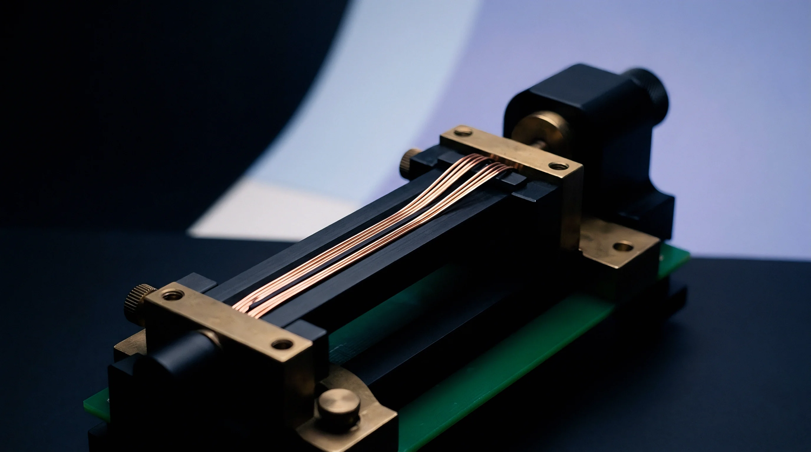

Speckle
Contact-free optical metrology resolves the mechanical boundary limits of furnace calibration. High-temperature 2D and stereo Digital Image Correlation systems measure displacement and surface strain fields directly through quartz optical viewports. Operating DIC at 1000 degrees Celsius invalidates standard surface preparation, as conventional organic black-and-white lacquers incinerate below 300 degrees Celsius.
Surface patterning demands pulsed aerosol deposition of micro-scale alumina or zirconia ceramic oxides, or high-temperature ceramic glazes enriched with cobalt oxide. The resulting surface patterns retain tracking contrast up to 1200 degrees Celsius without flaking off under mechanical expansion.

Can Optical Access Maintain Traceable Resolution at Extreme Heat?
Incandescence destroys raw optical strain accuracy once temperatures climb above 700 degrees Celsius. Thermal radiation from the sensor package and furnace interior emits heavy blackbody radiation across visible wavelengths, blinding image sensors and reducing correlation speckle contrast to zero. To counter this photon flood, illumination systems pair ultraviolet LED arrays centered at 365 nanometers with matching narrow bandpass optical filters installed on telecentric imaging lenses, or use blue LED lasers operating at 405 nanometers as high-flux coherent sources.
The filter suppresses radiant infrared emissions from the sample, passing only reflected short-wavelength photons back to the monochrome sensor.
Optical blue-filtering at 405 nanometers reduces thermal incandescence interference, preserving correlation contrast across extreme heating regimes.
Convective air currents inside the furnace and outside the viewport fluctuate thermal density gradients, causing severe refractive index shifts along the optical path. Uncorrected heat shimmer manifests as pseudo-strain oscillations reaching 400 microstrain peak-to-peak in static conditions. Countering this effect requires evacuating the test chamber to high vacuum below 1e-4 millibar, or encasing the optical line of sight within water-cooled quartz viewing tubes continually purged with laminar helium gas.
Table 2 details the performance trade-offs found across standard optical strain measurement techniques when applied inside thermal chambers.
| Measurement Technique | Field of View | Spatial Resolution | Strain Uncertainty (k=2) | Thermal Limit (C) | Thermal Shimmer Sensitivity |
|---|---|---|---|---|---|
| Stereo DIC (UV Filtered) | 10 mm x 10 mm | 15 um | +/- 25 microstrain | 1200 | Moderate (Requires Purge) |
| Electronic Speckle Interferometry | 5 mm x 5 mm | 2 um | +/- 5 microstrain | 800 | Severe (Requires Vacuum) |
| Moire Interferometry | 20 mm x 20 mm | 25 um | +/- 15 microstrain | 700 | High (Requires Enclosure) |
| Laser Dynamic Extensometry | 1 mm Point Gauge | 50 um | +/- 40 microstrain | 1400 | Low (Single Line Path) |
Calibration of the optical system itself must comply with VDI/VDE 2626 guidelines. Ceramic calibration targets carrying photolithographically deposited chromium dots provide the dimensional baseline. These targets feature glass-ceramic low-expansion substrates to prevent scale distortion during warm-up routines.
Technicians verify magnification factors and optical distortion parameters before every high-temperature test run, since a shifted lens element from ambient room heating will skew apparent strain readings by several dozen microstrain per hour.

Lead
Signal interconnects compromise more high-temperature MEMS calibration runs than transducer element failures. Standard copper and aluminum micro-wire bonds fail completely via melting, severe oxidation, or rapid intermetallic diffusion. Gold wire bonds subjected to 600 degrees Celsius on aluminum metallization pads create gold-aluminum intermetallic compounds: the destructive Phase Purple plague that produces voids and mechanical fracture within hours.
Reliable electrical delivery to wide-bandgap dies relies on 25-micrometer platinum wires thermo-sonically bonded to titanium-platinum-gold or nickel-silicide ohmic contact pads. Platinum interconnects resist oxidation across the entire thermal envelope, preserving low contact resistance.
Thermal electromotive force represents an insidious uncertainty contributor across high-temperature cabling routes. The Seebeck effect generates parasitic direct-current voltages at every junction of dissimilar conductors subjected to a spatial thermal gradient. A junction between a platinum bond wire and an external mineral-insulated nickel-chromium lead running through a furnace wall gradient of 400 degrees Celsius produces millivolt-level offset voltages.
Because piezoresistive wheatstone bridges yield full-scale signal outputs of only tens of millivolts, an uncompensated Seebeck offset simulates hundreds of microstrain units of false mechanical load.
- Mineral insulated cabling uses high-purity magnesium oxide powder insulation sheathed in Inconel 600 to prevent signal wire degradation while suppressing leakage currents to ground above 500 degrees Celsius.
- Alternating current bridge excitation reverses input voltage polarities sequentially at a fixed carrier frequency between 1 and 5 kilohertz, allowing output demodulators to subtract out non-inverting direct-current thermal electromotive forces entirely.
- Three-wire quarter-bridge wiring provides symmetrical lead resistance tracking throughout furnace temperature zones, cancelling out temperature-induced lead wire resistance swings inside the bridge completion network.
- High-temperature inorganic adhesives based on alumina-silicate cements anchor wire lines mechanically to the substrate, preventing destructive structural vibrations from stressing micro-scale wire bonds during dynamic load cycles.
Parasitic dielectric breakdown of packaging insulators corrupts calibration data as temperatures peak. Ceramic alumina carriers lose electrical resistivity exponentially as operating temperatures climb past 700 degrees Celsius. Substrate leakage resistances collapse from gigaohms down to hundreds of kiloohms, shunting the piezoresistive arms of micro-strain bridges.
Laboratory test leads must verify isolation resistance between signal traces and chassis ground continuously throughout the calibration sweep. A drop below 10 megohms compromises measurement fidelity beyond mathematical rescue.
The standard procurement line clause requires supplier test data to identify exact contact metallization systems alongside wire bonding materials. When a vendor substitutes gold-palladium alloy wire without updating lead calibration sheets, the resulting thermal coefficient swings wipe out the transducer calibration guarantee.

Drift
Static calibration accuracy decays the moment a transducer sustains peak operating conditions over extended periods. High-temperature zero-point drift stems from physical degradation phenomena occurring simultaneously: atomic diffusion across thin films, crystal lattice defect relaxation within the semiconductor membrane, and creep within the adhesive bonding layer. Silicon carbide sensors show substantial contact resistance shifts when exposed to 600 degrees Celsius oxygen environments, as residual oxygen molecules diffuse through passivation layers and form non-stoichiometric silicon oxide interfaces.
This oxidation permanently alters the base un-strained bridge resistance balance, registering as a persistent zero-point offset.
Creep in high-temperature ceramic cement bonding layers degrades mechanical load transfer, dropping measured strain values during extended isothermal holds.
Separating apparent strain from actual mechanical deformation requires a structured calibration calculation sequence. The calculation reconciles physical thermal expansion against electronic resistance adjustments across the full operating range:
- Run an isothermal baseline sweep at zero mechanical load from 20 degrees Celsius to peak calibration temperature, recording bridge output voltage at 50-degree stabilization intervals.
- Fit a third-order polynomial curve to the resulting thermal response profile to quantify the specific Apparent Strain curve for the individual sensor and test coupon assembly.
- Apply stepped mechanical loads using the deadweight lever frame at each isothermal hold, extracting the raw uncorrected output span across multiple loading cycles.
- Subtract the apparent thermal strain component algebraically from the raw output data collected during combined thermo-mechanical loading cycles.
- Compute the true Gauge Factor variation across the full temperature range by normalizing corrected output voltage sweeps against optical extensometer references.
Calibration labs frequently balance sensor lifespan warranties against recalibration intervals. Published specifications may claim an initial gauge accuracy of 1 percent, but at 750 degrees Celsius, silicon carbide piezoresistors show baseline resistance drifts ranging from 0.5 to 2.0 percent per 100 hours of continuous operation depending on packaging sealing integrity. Without scheduled in-situ zero-balance checks, an uncorrected transducer drifts outside its specified accuracy envelope before its third operational week concludes.

Budget
Formulating a defensible uncertainty budget for high-temperature micro-strain measurements requires summing orthogonal error contributors according to the Guide to the Expression of Uncertainty in Measurement. A simple room-temperature budget covers load cell fidelity, bridge amplifier non-linearity, and specimen cross-section tolerances. At 800 degrees Celsius, thermal terms become the dominant sources of expanded uncertainty.
Table 3 breaks down a representative uncertainty budget for a silicon carbide MEMS strain sensor calibrated within an isothermal furnace using four-point bending and stereo-DIC optical verification.
| Uncertainty Source | Probability Distribution | Standard Uncertainty (+/- microstrain) | Sensitivity Coefficient | Uncertainty Contribution (+/- microstrain) | |
|---|---|---|---|---|---|
| Optical DIC Displacement Tracking | Normal | 12.5 | 1.0 | 12.5 | |
| Furnace Thermal Gradient (+/- 1.5 C) | Rectangular | 0.87 | 14.2 ue/C | 12.3 | |
| Thermal EMF Rectification Residuals | Rectangular | 4.5 | 1.0 | 4.5 | |
| Apparent Strain Polynomial Fit Error | Normal | 8.0 | 1.0 | 8.0 | |
| Mechanical Loading Fixture Friction | Triangular | 5.2 | 1.0 | 5.2 | |
| Substrate/Adhesive Shear Creep | U-Shaped | 9.1 | 1.0 | 9.1 | |
| Combined Standard Uncertainty: 21.6 microstrain | Expanded Uncertainty (k=2, 95% Confidence): +/- 43.2 microstrain | |||||
Consider a practical calibration procurement scenario involving a lot of 50 wide-bandgap strain transducers destined for aerodynamic turbine blade testing. The application demands strain tracking over a range of 0 to 1000 microstrain at 800 degrees Celsius with an allowable error envelope of +/- 50 microstrain. Relying solely on room-temperature factory datasheets citing +/- 0.5 percent span accuracy suggests an apparent +/- 5 microstrain tolerance window.
Entering the calculated high-temperature expanded uncertainty of +/- 43.2 microstrain leaves an operating margin of merely 6.8 microstrain. Any minor thermal transient exceeding the furnace baseline consumes the entire remaining tolerance band.
Tightening this tolerance band demands substantial capital allocation. Suppressing the furnace spatial gradient from 1.5 degrees Celsius down to 0.5 degrees Celsius requires custom multi-zone gold-coated parabolic reflector chambers, driving the calibration bench tooling cost up significantly. Reducing optical DIC noise necessitates migrating from open viewing ports to high-vacuum quartz containment cells.
Each decimal place of confirmed accuracy at extreme temperatures requires exponential capital expenditure, transforming an economical component selection into a costly laboratory enterprise.
Field installations face unresolvable disputes when attempting to differentiate between base substrate creep and true transducer piezoresistive drift. When an assembled turbine component operates under continuous load at 850 degrees Celsius for 500 hours, physical metal creep and semiconductor defect migration generate identical directional resistance shifts in the monitoring bridge. Determining which fraction of the signal shift belongs to the alloy and which to the transducer remains an open calibration challenge.