Dynamic Mechanical Analysis Fixture Calibration for Polyimide Adhesives
Accurate polyimide modulus measurement demands fixture compliance subtraction, melting standard calibration, and dynamic clamp tracking across transition.


Compliance
Glassy polymers present severe calibration traps. When evaluating polyimide films and cured structural adhesives below their glass transition, specimen storage moduli span between 2.5 GPa and 4.2 GPa at 25 °C. At this level of rigidity, the raw displacement measured by the instrument sensor does not reflect pure specimen deformation. Transducers measure composite displacement.
The measured displacement represents the mechanical series combination of specimen strain, drive shaft flexure, clamp bracket bending, and instrument frame elasticity.

Instrument Stiffness Corrections
Deformation recorded by the linear variable differential transformer combines specimen strain with structural deflection across the drive shaft, pushrod, and grips. Treating the test system as two springs in series yields an exact relation: the inverse of measured stiffness equals the inverse of sample stiffness added to the inverse of fixture stiffness. If the fixture stiffness calibration is omitted, the software assumes an infinitely rigid loading assembly.
Stiff fixtures preserve measurement fidelity.
To quantify this error mechanism, consider a typical tensile calibration scenario for a B-stage polyimide adhesive film cast on a release liner and cured to a free-standing strip. Assume specimen length between clamp faces equals 15.0 mm, width equals 5.0 mm, and film thickness equals 0.050 mm (50 µm). The cross-sectional area equals 0.250 mm² (2.50 × 10⁻⁷ m²).
Assume true tensile storage modulus of the polyimide equals 3.20 GPa (3.20 × 10⁹ N/m²). True sample stiffness calculates directly as:
K_sample = (3.20 × 10⁹ N/m² × 2.50 × 10⁻⁷ m²) / 0.015 m = 53,333 N/m.
Now consider an uncalibrated tension film fixture with an empirical system compliance of 1.20 × 10⁻⁵ m/N, corresponding to a fixture stiffness K_fixture of 83,333 N/m. The total compliance observed by the drive motor becomes the direct sum:
C_measured = (1 / 53,333 N/m) + (1.20 × 10⁻⁵ m/N) = 1.875 × 10⁻⁵ m/N + 1.20 × 10⁻⁵ m/N = 3.075 × 10⁻⁵ m/N.
Inverting this sum yields an apparent stiffness K_measured of 32,520 N/m. When the software calculates apparent storage modulus from this raw stiffness using sample geometry, it derives:
E_apparent = (32,520 N/m × 0.015 m) / 2.50 × 10⁻⁷ m² = 1.95 GPa.
A raw tensile measurement on 50-micrometer polyimide film underestimates true storage modulus by thirty-nine percent when fixture rigidity falls below eighty thousand newtons per meter.
The uncorrected apparatus underreports true glassy modulus by 39.1 percent. This discrepancy traces entirely to uncalibrated fixture compliance. Calibrating fixture stiffness requires executing an oscillatory displacement sweep across a rigid calibration standard, typically a monolithic block of 6061-T6 aluminum or 304 stainless steel with a calculated stiffness exceeding 5.0 × 10⁶ N/m.
The recorded load-to-displacement ratio defines the compliance baseline subtracted from all subsequent sample files.
| Fixture Geometry | Standard Specimen Size (mm) | True Sample Modulus (GPa) | Fixture Stiffness Baseline (N/m) | Uncorrected Measured Modulus (GPa) | Systematic Error (%) |
|---|---|---|---|---|---|
| Tension Film Strip | 15.0 × 5.0 × 0.05 | 3.20 | 8.33 × 10⁴ | 1.95 | -39.1 |
| Tension Thick Bar | 20.0 × 6.0 × 1.50 | 3.50 | 1.10 × 10⁵ | 0.51 | -85.4 |
| Three-Point Bending | 20.0 × 10.0 × 2.0 | 3.40 | 4.50 × 10⁵ | 2.88 | -15.3 |
| Dual Cantilever | 35.0 × 12.0 × 2.5 | 3.10 | 2.80 × 10⁵ | 1.74 | -43.9 |
| Double Lap Shear | 10.0 × 10.0 × 0.10 | 1.15 (Shear G’) | 6.20 × 10⁶ | 1.12 | -2.6 |
Failing to baseline and subtract fixture compliance causes production facilities to reject compliant polyimide batches whose glassy modulus appears out of specification, generating unwarranted dispute costs and scrapped material inventories.


Clamp
Polyimide films undergo lateral Poisson contraction and thermal softening as temperature crosses three hundred degrees Celsius. Thin films exacerbate clamping errors. Modulus values drop three decades.
At 25 °C, a high-temperature polyimide adhesive exists in an unyielding glassy state, whereas at 360 °C, the storage modulus drops from 3.2 GPa to 1.8 MPa. This drop alters contact mechanics at the clamping boundaries.
Grip Pressure and Dimensional Loss
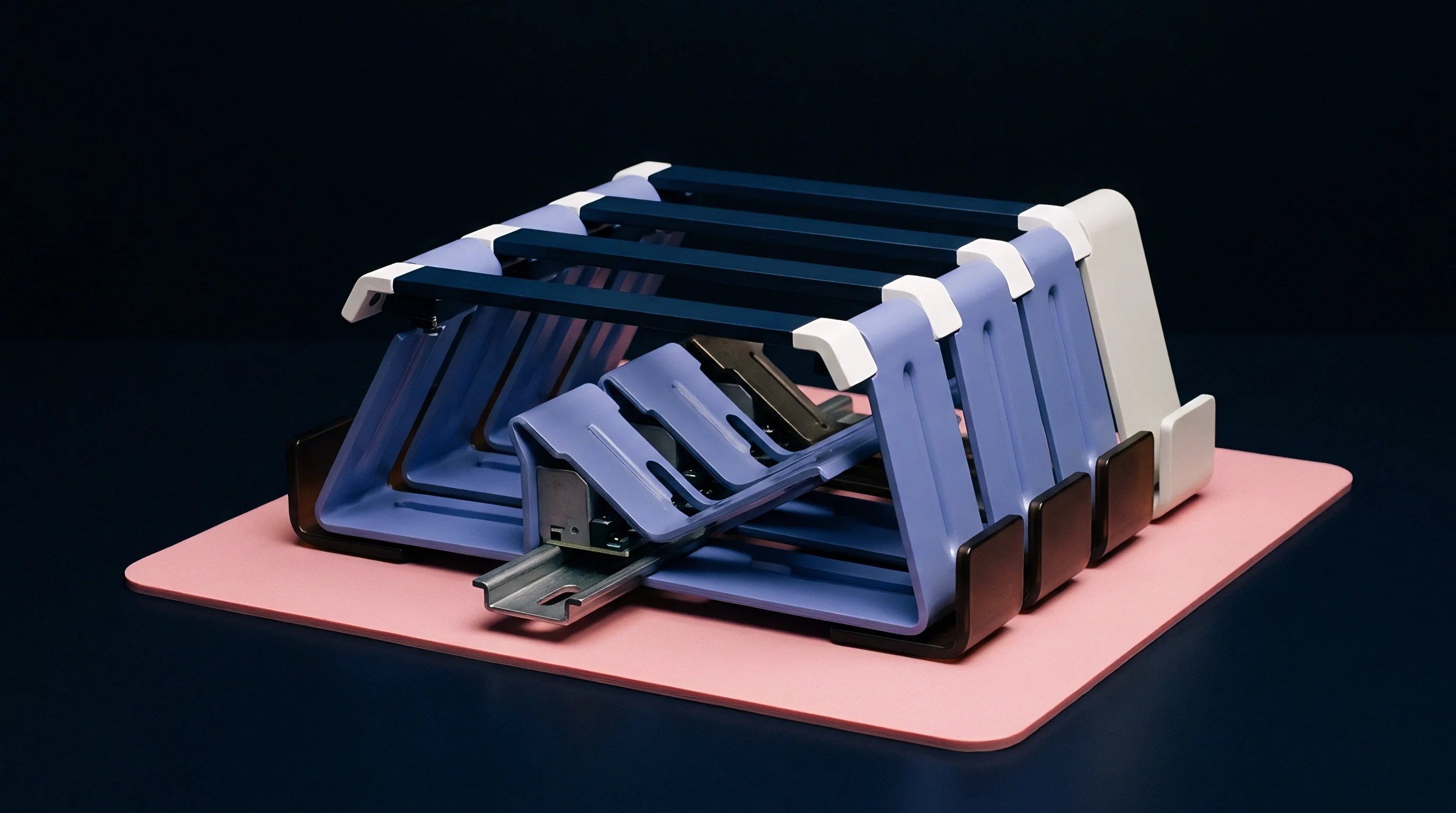
Viscoelastic stress relaxation at elevated temperatures causes holding bolts to lose seating force. Screws relax under elevated heat. Clamp screws torqued to 0.45 N·m at room temperature experience thermal expansion differences between the titanium clamp frame and the high-nickel alloy fastener.
As the polyimide softens, the constant clamp gap allows the film to thin under the clamping land, leading to sample slippage.
Slippage creates fictitious damping peaks. The displacement sensor records the displacement of the moving clamp jaw relative to the fixed bracket. When the film slips within the grip face, the displacement motor drives past the sample boundary.
The software interprets this boundary slide as viscous flow in the adhesive layer, producing massive false peaks in loss modulus and tan delta. Dynamic clamp calibration incorporates auto-strain and dynamic tracking force adjustments.
- Thermal screw unseating occurs when mismatched expansion coefficients between Inconel clamp bolts and titanium bodies relax clamping forces above two hundred degrees Celsius.
- Boundary pinch deformation crushes the softened polyimide film at the jaw edge, inducing localized necking that masquerades as an early rubbery transition.
- Friction slip wandering introduces an artificial phase lag between command force and recorded displacement, distorting tan delta peak magnitudes by up to forty percent.
- Buckling artifact generation takes place during oscillatory return cycles when dynamic amplitude exceeds static tension bias, driving the thin film into out-of-plane flexure.
Calibrating clamp tracking requires setting the static force tracking ratio to 125 percent of the dynamic oscillatory force. If the dynamic drive demands an oscillatory force of 0.80 N to maintain a 15 µm displacement amplitude, the static motor must apply a constant 1.00 N tensile preload. This preload prevents specimen buckling during compressive cycles.
As the film expands thermally during a temperature ramp, the automated actuator repositions the clamp baseline to preserve this exact ratio.
Tension fixtures holding thin polyimide films maintain measurement stability when clamping torque scales in direct proportion to specimen glass transition boundaries rather than ambient room-temperature thickness.

Furnace
Thermocouples positioned four millimeters above a specimen record ambient gas temperature rather than internal core values. Polyimide adhesives require operational characterization extending from 20 °C to 450 °C. Across this broad thermal window, heat transfer shifts between convective flow and radiative emission. Inert gas accelerates thermal conduction.
Nitrogen purge gas retards oxidation. Thermal lag creates an offset between the sample temperature and the furnace control sensor.

Thermal Lag and Environmental Chamber Gradients
Calibration of the furnace enclosure relies on certified melting point standards under identical dynamic heating rates, following ASTM E1867 guidelines. Placing pure metal foils within a tension fixture allows detection of phase change through mechanical yield or drop-point elongation. Pure indium melts at 156.60 °C, tin at 231.93 °C, lead at 327.46 °C, and zinc at 419.53 °C. Fast heating rates inflate transition values.
| Heating Rate (°C/min) | Purge Gas | Purge Flow Rate (mL/min) | Observed Transition (°C) | Thermal Lag Correction (°C) | Expanded Uncertainty (k=2, °C) |
|---|---|---|---|---|---|
| 1.0 | Helium | 200 | 328.05 | -0.59 | ±0.35 |
| 2.0 | Helium | 200 | 328.72 | -1.26 | ±0.40 |
| 5.0 | Helium | 200 | 330.41 | -2.95 | ±0.52 |
| 2.0 | Nitrogen | 200 | 331.86 | -4.40 | ±0.65 |
| 5.0 | Nitrogen | 200 | 336.12 | -8.66 | ±0.88 |
| 10.0 | Nitrogen | 200 | 343.25 | -15.79 | ±1.24 |
| 5.0 | Air | 200 | 336.88 | -9.42 | ±0.94 |
Helium gas delivers superior thermal conductivity compared to dry nitrogen, reducing thermal lag across a 5 °C/min sweep from 8.66 °C down to 2.95 °C at 327 °C. Calibration tables developed in nitrogen cannot correct runs conducted under helium or air.
Purging test enclosures with high-conductivity gas collapses thermal differentials faster than extending isothermal dwell durations.

Where Does Thermal Lag Distort Glass Transition Points?
Dynamic mechanical spectra gathered across multiple heating rates reveal systematic upward shifts in loss modulus peak positions. When testing an uncured or partially imidized polyimide adhesive film at 10 °C/min, the recorded glass transition temperature can appear 16 °C higher than the true thermodynamic transition recorded at quasi-static heating rates (0.5 °C/min). Thermal lag compounds kinetic reaction shifts during cure monitoring.
Solvent evaporation and ongoing imidization release water vapor, changing heat capacities dynamically.
Instrument suppliers frequently state that thermal lag remains negligible whenever heating rates stay below five degrees per minute in standard nitrogen atmospheres.


Shear
Adherend deflection distorts viscoelastic readings whenever adhesive layer stiffness approaches backing beam flexibility. Adherend bending pollutes pure shear fields. Cured polyimide structural adhesives often bond metallic or ceramic components rather than operating as free films.
Characterizing these adhesives in their native bondline configuration utilizes a symmetrical double lap shear sandwich geometry, adhering to ASTM D5279 or ISO 6721-6 standards.

Substrate Rigidity in Bondline Sandwich Geometries
Evaluating an adhesive film of 50 µm thickness bonded between stainless steel adherends introduces severe geometric sensitivity. Geometry errors multiply through cubic terms. In shear testing, the shear modulus G’ derives from the applied force, the shear area, and the layer thickness.
A three-micrometer error in measuring the cured bondline thickness translates to an immediate six percent error in calculated modulus.
- Zero displacement reference zeroing eliminates transducer gap offsets prior to mounting rigid substrates, preventing initial position biases that distort shear strain calculations.
- Blank adherend baseline execution records the parasitic flexural response of unbonded metal carrier bars across the complete operational temperature envelope, providing the numerical subtraction matrix for raw compliance.
- Bondline optical micrometer verification measures cured adhesive thickness across four perimeter quadrants with half-micrometer resolution, preventing cubic-power dimensional errors during modulus derivation.
- Dynamic amplitude sweep confirmation identifies the linear viscoelastic boundary at isothermal low-temperature holds, preventing strain-induced bondline microcracking during subsequent thermal ramps.
Calibrating the fixture demands accounting for the compliance of the adherend bars. Stainless steel carrier bars possess a finite shear modulus of 78 GPa. When testing a rigid, highly aromatic polyimide bondline below 200 °C, the localized shear deformation within the steel carrier constitutes four to seven percent of total recorded travel.
Specifying test execution under ISO 6721-6 obligates laboratories to document raw phase angles alongside geometry-corrected storage moduli to expose uncorrected instrument inertia.

What Drives Phase Angle Drift in Thin Bondlines?
Sub-milliradian transducer delay emerges from inertia adjustments in the moving drive bracket when testing high-loss adhesive layers. At 10 Hz oscillation frequencies, the mass of the moving shear clamp generates an inertial force that leads the actual displacement by 180 degrees. If the instrument firmware carries an outdated mass calibration file, this inertial force corrupts the measured phase angle delta.
For low-loss polyimides where tan delta drops below 0.005 in the glassy plateau, an inertia calibration error of 0.05 grams shifts tan delta into negative, physically impossible values.
Selecting the correct fixture demands matching sample physical form to loading geometry boundaries:
- Free-standing tensile geometry suits fully imidized unsupported films thicker than twenty-five micrometers having tensile storage moduli above two gigapascals.
- Dual cantilever clamping accommodates thick composite laminates or heavily reinforced polyimide prepregs where flexural stiffness prevents out-of-plane twisting during sweeps.
- Symmetrical double lap shear addresses paste adhesives and uncured precursor resins requiring rigid metallic carrier bars to sustain planar shear stresses during imidization reaction stages.
Whether non-linear edge stresses in high-temperature polyimide bondlines can be fully resolved through linear viscoelastic corrections without finite element calibration remains an open debate in thermal analysis metrology.


Settlement
Accredited calibration houses invoice between twelve hundred and three thousand dollars per fixture set for annual ISO 17025 verification cycles. Instrument software masks raw data. Uncalibrated hardware voids vendor warranties.
Commercial supply agreements for high-reliability polyimide adhesives used in semiconductor packaging and aerospace radomes routinely hinge on glass transition and storage modulus tolerances. When two independent testing facilities generate conflicting results from the same adhesive lot, calibration audit trails settle the dispute.

Interlaboratory Reproducibility and Standard Clauses
Disputed values trigger incoming lot rejections. A aerospace component specification might stipulate a minimum tensile storage modulus of 2.20 GPa at 250 °C and a glass transition onset of no less than 340 °C. If the receiving inspection laboratory uses an uncalibrated tension clamp lacking compliance compensation, their bench will report 1.45 GPa, failing the lot. Precise documentation settles quality disputes.
| Calibration Regime | Annual Maintenance Expense (USD) | Typical Storage Modulus Uncertainty (%) | Glass Transition Uncertainty (°C) | Commercial Dispute Exposure Level |
|---|---|---|---|---|
| Uncalibrated Factory Baseline | 0 | ±35 to ±50 | ±14.0 | Severe (High Rejection Rates) |
| Single-Point Factory Trim | 1,200 | ±15 to ±22 | ±6.5 | Moderate (Boundary Batch Disputes) |
| Full In-House Calibration (Multi-Standard) | 3,800 | ±4.5 to ±7.0 | ±2.0 | Low (Defensible Data Packages) |
| Accredited ISO 17025 Certified Package | 7,500 | ±2.0 to ±3.5 | ±0.8 | Negligible (Legally Binding Traceability) |
An enterprise qualifying a high-temperature polyimide bondline amortizes the calibration investment across scrap reduction and contract defense. A single disputed production batch of structural adhesive film represents forty thousand to two hundred thousand dollars in landed product value. Relying on unverified factory calibration constants introduces commercial risk that far exceeds the price of traceable verification blocks and mass calibration sets.
A contract specifying glass transition temperature without defining the exact mathematical inflection point invites immediate commercial dispute.
Mitigating this exposure requires explicit legal framing within the procurement documentation. Quality clauses in supply agreements eliminate ambiguity by defining test frequency, clamp torque limits, dynamic strain amplitude, heating rate, purge gas flow, and the exact mathematical inflection point defining glass transition.
Section 7.3 of ASTM D4065 establishes that dynamic mechanical properties reported without verified fixture compliance corrections and dynamic thermal lag compensation constitute uncertified engineering estimates rather than compliant material specifications.