PCB Layout Rules for Switched Capacitor Converters
Minimizing flying capacitor loop perimeter below eight millimeters on top copper layer shields switched capacitor converters from parasitic noise and breakdown.
Node
Switched capacitor converters achieve high power density by transferring charge through flying capacitors rather than storing energy in magnetic cores. Minimizing parasitic inductance along the high-frequency charge transfer paths dictates the physical arrangement of the active switches and passive storage elements. Placing the flying capacitor directly adjacent to the switching pin terminals cuts parasitic loop trace length below two millimeters, preventing high-frequency voltage spikes across the internal field-effect transistors.
Direct trace connections without layer transitions hold parasitic trace inductance under one nanohenry, which suppresses ringing and protects internal power switches from breakdown during phase switches.
Tight placement controls switching spikes. High frequency shifts performance. Ceramic dielectrics drift with voltage.
Input and output decoupling capacitors demand symmetric placement around the IC pins to maintain continuous current paths and reduce radiated electromagnetic interference.

Flying Capacitor Loop Reduction
Switched capacitor topologies shift charge between input, flying, and output capacitors at frequencies spanning 100 kHz to over 5 MHz. The loop formed by the integrated switch network, the flying capacitor terminals, and the return ground path carries pulsed currents with rise times under five nanoseconds. Truncating this physical path represents the most effective layout measure for controlling parasitic inductance.
- Position the flying capacitor on the top assembly layer directly adjacent to the IC flying capacitor pins without placing vias inside the primary current loop.
- Route the flying capacitor traces using wide copper pours matching or exceeding the land pad width to lower parasitic resistance and trace inductance.
- Keep the total loop perimeter formed by the internal switches and the external flying capacitor under eight millimeters.
- Insert a dedicated ground reference return fill on the immediate inner layer directly beneath the flying capacitor components.
Placing flying capacitors on the outer layer directly above an uninterrupted inner ground plane holds loop inductance low enough to prevent switch breakdown.

Input and Output Decoupling Geometry
Input capacitors supply transient charge during charging phases, while output capacitors absorb energy during discharge phases. Placing these components with asymmetric trace lengths introduces differential voltage drops across the terminal pins. Symmetric current return paths keep ground bouncing within safe noise margins for sensitive analog enable and feedback circuitry.
Vias inserted into high-current paths introduce approximately 0.5 to 1.0 nH of parasitic inductance per via, depending on barrel length and drill diameter. Connecting decoupling capacitors directly to IC pins on the component side avoids via inductance within the primary switching loop. Ground terminals of input and output capacitors should meet at a single low-impedance copper pad before connecting to the main board ground plane through a thermal via array.
Layout errors in high-current charge pump paths elevate parasitic inductance, causing excessive voltage overshoot that accelerates silicon breakdown and triggers thermal shutdown during peak load transitions.


Foil
Board layer construction determines thermal dissipation pathways and electromagnetic shielding quality for high-density power converters. Copper weight selection directly impacts both trace resistance and the cross-sectional area available for conduction. Utilizing two-ounce copper outer layers lowers trace conduction losses while spreading heat across the printed circuit assembly.
Inner ground planes function as heat sinks and image planes, redirecting high-frequency currents away from external signal traces.
Heat flows through copper fills. Copper traces add resistance. Thermal relief vias add inductance.
Unbroken ground pours directly beneath switching nodes shield low-level control lines from capacitive noise coupling.
Layer Stackup and Plane Continuity
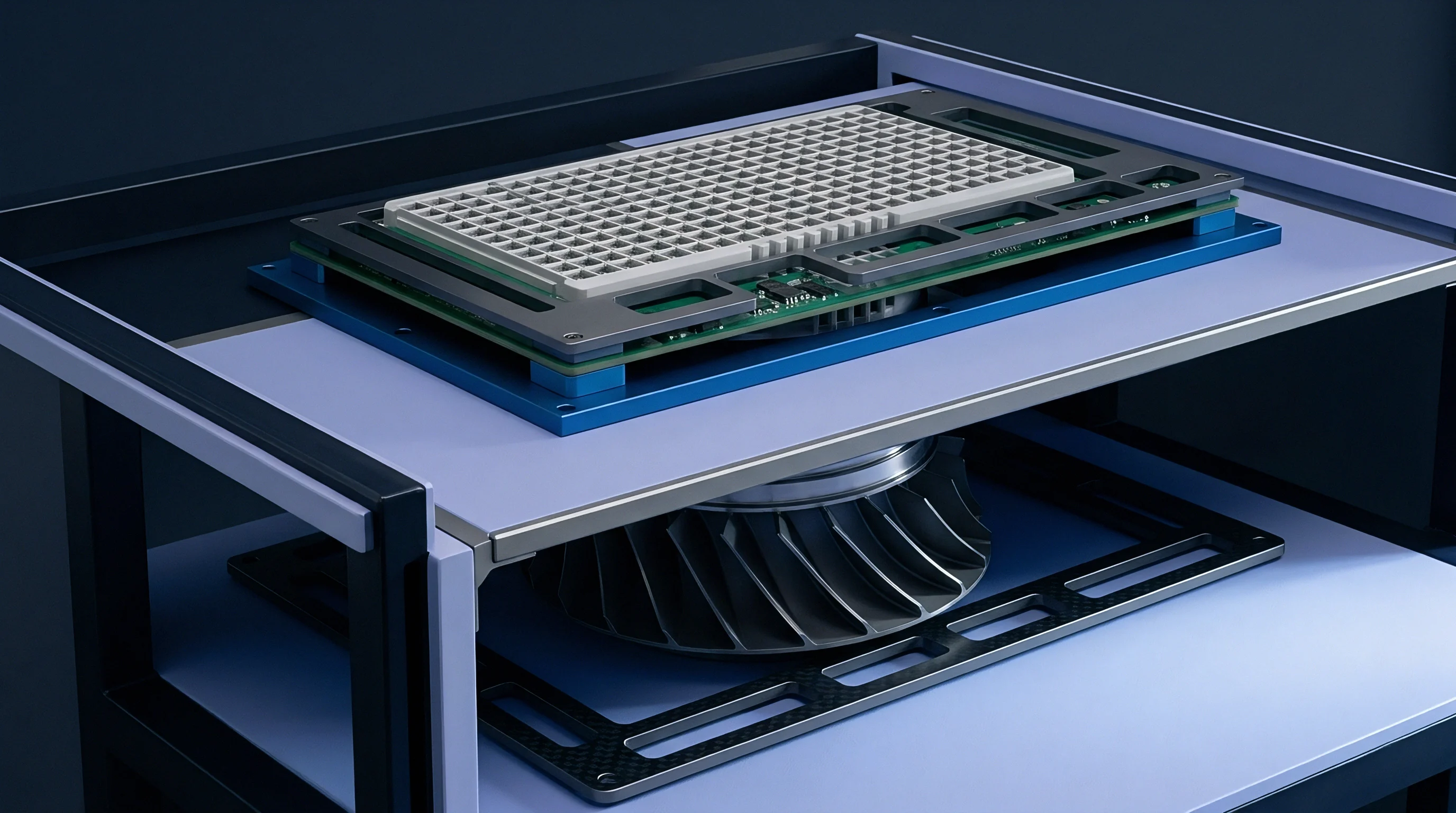
A four-layer board stackup provides the minimum structural baseline for low-noise switched capacitor converter designs. The primary component layer houses the converter IC, flying capacitors, and decoupling filters. Layer two operates as an uninterrupted ground plane, providing a low-impedance image path for switching currents flowing on layer one.
Splitting ground planes under switched capacitor ICs creates slot antennas that radiate high-frequency harmonics across the board assembly. Continuous ground copper under the flying capacitor nodes minimizes common-mode noise generation. Signal routing for enable, power-good, and output feedback signals must reside on layer three or four, shielded from the switching nodes by the solid ground plane on layer two.
| Package Size | Capacitance Range (µF) | Parasitic Inductance (pH) | Typical ESR (mΩ) | Recommended Trace Width (mm) |
|---|---|---|---|---|
| 0402 (1005 Metric) | 0.1 to 2.2 | 350 | 12 | 0.30 |
| 0603 (1608 Metric) | 1.0 to 10.0 | 500 | 8 | 0.50 |
| 0805 (2012 Metric) | 4.7 to 22.0 | 750 | 5 | 0.80 |
| 1206 (3216 Metric) | 10.0 to 47.0 | 1050 | 3 | 1.20 |

Thermal via Arrays and Copper Thins
Switched capacitor regulators dissipate power primarily through switch resistance and capacitor ESR rather than core losses. Conductive thermal pathways from the IC exposed pad to internal and bottom copper layers drop die temperature rise under maximum load currents. Arraying small-diameter vias directly beneath the IC thermal pad yields a lower thermal resistance path than relying solely on surface copper conduction.
Via drill diameters of 0.3 mm with a 0.6 mm land pattern prevent solder wicking out of the pad while maintaining structural copper cross-sections. Pitching thermal vias 0.8 mm apart inside the exposed pad perimeter maximizes heat transfer down to internal ground planes. Surface copper fills surrounding the thermal pad should extend at least five millimeters beyond the IC perimeter to facilitate convection cooling into ambient air.
A four-layer stackup featuring a solid ground plane on layer two drops radiated noise by more than 20 dB compared to two-layer designs under identical 2 A load switching conditions.
Placing solid copper pours on top layers without thermal splits delivers lower operating temperatures and cleaner switching waveforms.


Ripple
Output voltage variation in charge pump circuits stems from charging currents flowing through equivalent series resistance and periodic discharging of output capacitors. Switch transition speed and switching frequency directly dictate the fundamental frequency of this output voltage variation. Managing output noise requires tight component selection alongside precise layout execution to keep parasitic series inductance from corrupting sensitive downstream loads.
Current spikes induce noise. Compact loops drop radiated emissions. Ground plane splits ruin efficiency.
Paralleling different capacitor package sizes attenuates high-frequency ripple components across broader frequency bandwidths.

Parasitic Inductance and Switching Noise
High-frequency output noise consists of step-voltage spikes overlaid on the fundamental switching ripple waveform. Voltage spikes occur during phase transitions when fast current steps encounter stray inductance in the output trace and decoupling capacitor leads. Using wide, short traces between the IC output pins and the output filter array reduces this inductance.
Paralleling a small 0.1 µF 0402 ceramic capacitor alongside a 10 µF 0805 bulk capacitor drops high-frequency impedance. The 0402 package exhibits low parasitic inductance, shunting high-frequency transition spikes to ground, while the larger 0805 capacitor maintains charge storage for fundamental ripple suppression. Routing output sense lines away from flying capacitor nodes prevents switching noise from coupling into the regulator feedback control loop.

What Limits Output Voltage Accuracy under Load?
Load regulation degrades when high current flows across non-negligible trace resistance between the converter output pad and the point of load. Sensing the output voltage directly at the load terminals compensates for resistive voltage drops across intervening board traces. Connecting the feedback resistor network to the converter pin via a dedicated, shielded trace guarantees accurate voltage regulation under fluctuating load conditions.
Trace resistance on a standard one-ounce copper layer measures approximately 0.5 mΩ per square. A trace carrying 3 A over a length of 20 mm with a width of 1 mm introduces a 30 mV DC drop. Placing the feedback resistor divider close to the IC control pins while extending the feedback sense line to the load minimizes noise pickup on the high-impedance feedback node.
Output ripple amplitude scales inversely with switching frequency and output capacitance, while high-frequency spike amplitude depends entirely on parasitic loop inductance.
Can optimized PCB trace geometry eliminate the need for post-regulator low-dropout linear filters in low-noise RF sensor applications?

Variant
Selecting the optimal physical implementation for a switched capacitor power supply involves evaluating discrete ICs, module-on-board assemblies, and fully integrated power modules. Discrete designs allow fine tuning of capacitor quality and land patterns but occupy substantial board real estate. Integrated modules embed flying capacitors and active switches within a single land pattern package, reducing layout complexity at a higher component unit cost.
Component clearance prevents shorting. Stencil aperture thickness affects yield. Package footprint selection balances physical board area against engineering integration effort.

Discrete Converter IC versus Integrated Micro Module
Discrete implementations require layout engineers to place up to four ceramic capacitors within tight geometric constraints around a tiny QFN or WLCSP IC package. This approach yields the lowest bill of materials cost at high production volumes. However, placement errors, via inductances, and trace parasitics remain board-level risks that must be verified through prototype bench tests.
Integrated micro-modules encapsulate the silicon die and internal flying capacitors into a single LGA or BGA footprint. These modules present a fully optimized internal layout, reducing parasitic inductance to levels unattainable on standard PCBs. The trade-off shifts from manual board optimization to higher component acquisition costs and specific reflow profile restrictions.
| Implementation Form | Board Area (mm²) | Layout Complexity | Unit Cost Baseline | Engineering Bring-up Weeks |
|---|---|---|---|---|
| Discrete QFN + External Caps | 45 to 80 | High | 1.0x | 3 to 5 |
| WLCSP + 0201 External Caps | 15 to 30 | Very High | 1.4x | 4 to 6 |
| Integrated LGA Micro-Module | 10 to 20 | Low | 2.8x | 1 to 2 |
| System-in-Package (SiP) Solution | 8 to 15 | Low | 3.5x | 1 to 2 |

Bill of Materials Cost Breakdown across Volumes
Evaluating total landed cost across production volumes dictates whether a discrete component approach or an integrated module makes financial sense for a given project. At volumes below 10,000 units, the engineering cost of optimizing a discrete layout exceeds the component price premium of an integrated module.
- Discrete QFN Architecture delivers low component unit costs but demands higher layout effort and extra board footprint.
- WLCSP Layout Design minimizes overall footprint area while introducing strict manufacturing tolerance and board assembly requirements.
- Integrated LGA Module lowers design cycle risk and board space consumption while elevating per-unit bill of materials cost.
- System-In-Package Module combines active silicon and passive passives into a single tested component with turnkey design integration.
Suppliers often claim their integrated modules eliminate layout sensitivity entirely, though improper ground pad heat sinking still leads to premature thermal throttling under sustained heavy loads.

Audit
Verifying layout execution requires rigorous physical inspection, dimensional qualification, and thermal testing before approving designs for high-volume manufacturing. Board fabrication tolerances, solder mask alignment, and reflow stencil aperture designs directly affect manufacturing yields for fine-pitch power converter packages. Establishing strict qualification criteria prevents field failures caused by solder bridging, pad lifting, or dielectric degradation.
Board thickness dictates via aspect ratios. Placement controls switching spikes. Systematic inspection of first-article PCB assemblies validates land pattern compliance against component IPC standards.
Manufacturing Tolerances and Reflow Qualification
Land patterns for fine-pitch QFN and WLCSP converter packages require precise solder mask registration to avoid exposing ground copper near active signal pads. Solder mask defined (SMD) pads provide uniform land shapes for ball grid arrays, whereas non-solder mask defined (NSMD) pads are preferred for QFN lead frames to improve mechanical joint anchorage.
Stencil aperture design dictates solder paste volume delivered to the converter exposed pad and surface-mount capacitors. Reducing stencil coverage on the center exposed pad to 60 or 70 percent using a window-pane pattern prevents thermal pad floating, which can cause open circuits on peripheral signal leads. Laser-cut stainless steel stencils with electropolished wall apertures ensure clean paste release on fine-pitch 0.4 mm land pads.
Reflow soldering profiles matching IPC/JEDEC J-STD-020 guidelines hold peak package body temperatures below 260°C to protect delicate ceramic capacitor dielectrics from thermal shock cracking.

Thermal Cycling and Solder Joint Fatigue
Switched capacitor converters experience localized thermal expansion during dynamic load steps. Differential thermal expansion between the silicon die, FR-4 substrate, and ceramic capacitors induces shear stress across solder joints. Thermal cycling tests performed per JESD22-A104 reveal solder joint fatigue failures if component footprints lack proper thermal relief geometry.
Inspecting post-test cross sections verifies intermetallic compound layer thickness and detects micro-cracks within the solder matrix. Maintaining solder joint fillet heights above 75 percent of the component termination height ensures long-term mechanical joint reliability under mechanical shock and vibration environments.
Per IPC-A-610 Class 3 standards, assembly lots exhibiting solder bridging, component tilt exceeding five degrees, or voiding exceeding 15 percent beneath thermal pads are rejected prior to final functional acceptance testing.