Thermopile Hot Junction Transient Thermal Attenuation under High Frequency Modulation
Modulating thermopiles past their thermal corner frequency attenuates Seebeck output by over twenty decibels per decade, demanding low-conductance cavity gases.
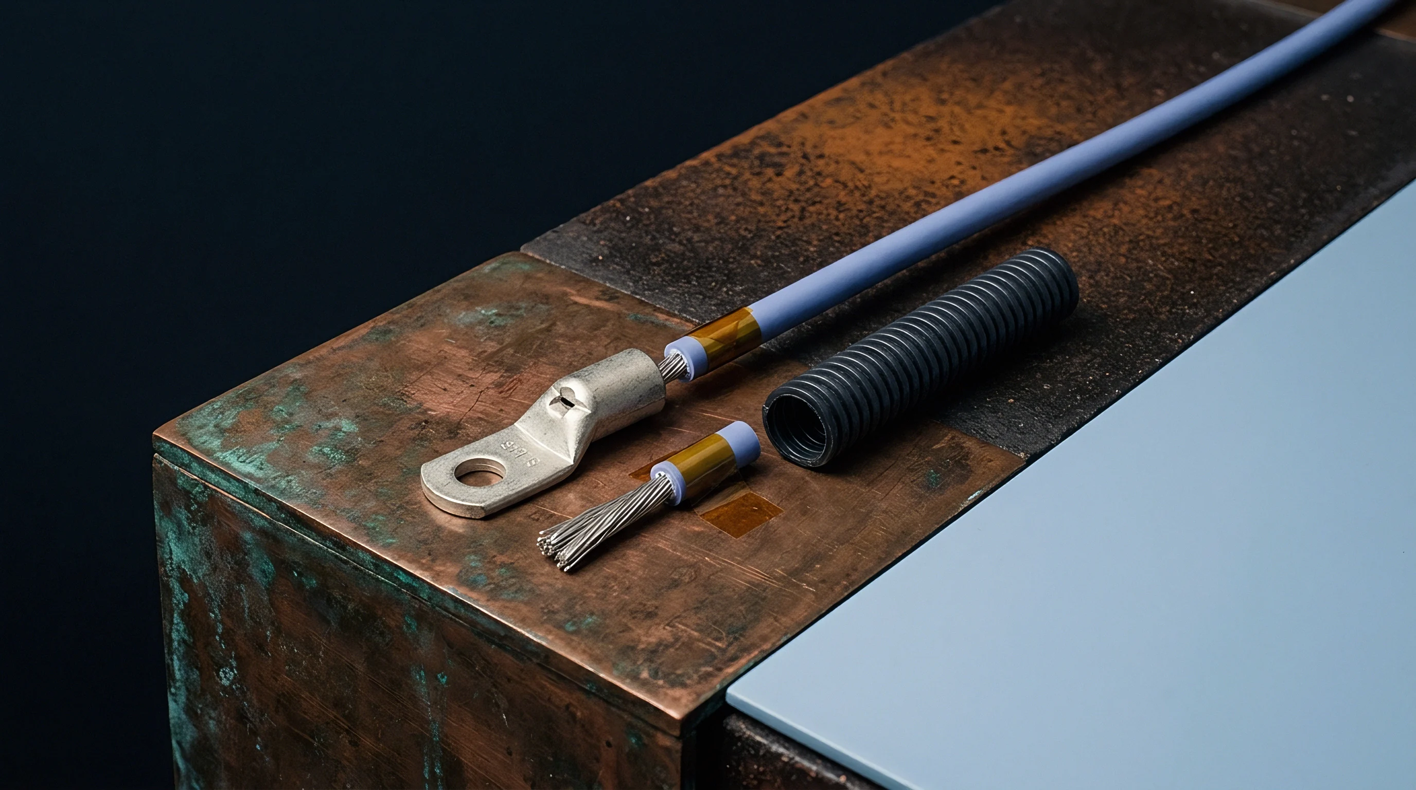

Membrane
Micro-machined thermopiles experience steep roll-off in Seebeck voltage when incident radiation fluctuates faster than the thermal diffusion transit time across the suspended thin-film absorber. Radiation striking the central target creates an instantaneous heat flux that conducts laterally through polysilicon, bismuth-telluride, or silicon-germanium thermoelements toward the heat sink rim on the bulk silicon wafer. Thermal capacitance residing in the dielectric support layer and absorber coating delays temperature accumulation at the active junctions.
Thin structures conduct sluggishly.
Energy balance on the suspended structure equates absorbed optical power to the sum of conductive losses, convective gas transfers, radiative dissipation, and sensible heat storage. Under steady optical flux, the temperature difference between the active thermocouple junction and the peripheral reference junction reaches an equilibrium determined purely by the thermal resistance of the supporting struts and the fill gas. Introducing high-frequency modulation forces the heat equation into the frequency domain, where volumetric heat capacity divides the steady-state thermal resistance by a complex thermal admittance term.
Thermal boundary resistance matters.
A 1.0-micrometer silicon nitride diaphragm with gold-black blackbody coating under square-wave optical chopping at 100 Hz yields 18.2 percent of its direct-current responsivity at 298 Kelvin.
Heat transfer mechanisms establish distinct parallel pathways between the active zone and the ambient die perimeter:
- Beam solid conduction transfers heat through the dielectric support arms and the patterned thermoelectric traces directly into the bulk silicon substrate frame.
- Cavity gas conduction dissipates thermal energy across the microscopic clearance gap separating the suspended micro-bridge from the floor of the etched silicon cavity.
- Radiative emission exchanges photons between the elevated hot junctions and the surrounding hermetic cap surfaces according to the Stefan-Boltzmann relationship.
- Interfacial thermal resistance restricts phonon transmission across boundaries between disparate deposited layers of dielectric passivation, metallization, and blackbody absorption coatings.
Each conduction channel presents a distinct time constant determined by local material diffusivity and geometry. The thermopile behaves as a distributed multi-stage low-pass filter rather than an ideal lumped single-pole system. Dielectric back-etch profiles create non-uniform thermal mass profiles across the span between center and edge.
Central junctions warm faster than intermediate junctions situated mid-span along the beam arrays, causing higher-order poles to appear in the transient thermal impedance transfer function at frequencies above 30 Hz.
Silicon conducts heat swiftly. Lateral dimensions and dielectric film thicknesses set the structural time constant. Standard low-stress silicon nitride layers with thicknesses between 0.8 and 1.2 micrometers exhibit a thermal conductivity near 2.5 to 3.2 W/(m·K), paired with a specific heat capacity of roughly 700 J/(kg·K).
Combining these material constants with typical bridge lengths between 150 and 350 micrometers yields fundamental thermal diffusion times between 8 and 25 milliseconds. Operating above these frequency limits forces hot junctions to experience partial thermal cycles, damping peak temperature excursions before thermal equilibrium develops.


Cutoff
Frequency response roll-off in thin-film thermoelectric detectors follows the complex thermal impedance between the hot junction and the isothermal package reference. As optical chop rates increase, thermal penetration depth shrinks proportionally to the inverse square root of the modulation frequency. Thermal waves attenuate exponentially as they propagate along the supporting beams toward the substrate cold junctions.
Phase lag accumulates rapidly.

Does Thermal Diffusion Limit Chopping Speed?
Direct modulation of the incident infrared beam at frequencies beyond 20 Hz reveals the transition from lumped-capacitance behavior into the one-dimensional thermal diffusion regime. At low frequencies, the Seebeck output tracks radiant flux with an amplitude response governed by the classic first-order break frequency. Beyond this corner, the effective heat transfer zone retreats from the supporting silicon rim into the interior of the dielectric diaphragm.
Thermal penetration depth drops below the physical length of the thermoelectric beams, decoupling hot junctions from their physical thermal sink and steepening the attenuation slope beyond twenty decibels per decade.
| Modulation Frequency (Hz) | Thermal Penetration Depth (micrometers) | Normalized Responsivity (dB) | Output Phase Lag (degrees) | Attenuation Ratio |
|---|---|---|---|---|
| 1.0 | 318.0 | -0.04 | -5.7 | 0.995 |
| 10.0 | 100.6 | -3.01 | -45.0 | 0.707 |
| 40.0 | 50.3 | -12.30 | -76.0 | 0.243 |
| 100.0 | 31.8 | -20.40 | -84.3 | 0.095 |
| 250.0 | 20.1 | -28.10 | -87.7 | 0.039 |
| 500.0 | 14.2 | -34.10 | -88.9 | 0.020 |
Chopper frequency shifts calibration. Output voltage drops while thermal gradient profiles shift across the serial junction pairs. The inner thermocouple pairs retain localized temperature elevation while outer thermocouple pairs experience complete thermal wash, failing to develop Seebeck potential.
This spatial variance distorts linearity across radiant intensity changes. Microvolt outputs shrink toward the Johnson noise floor of the thermocouple series resistance, degrading signal-to-noise ratios in gas correlation filter radiometers and nondispersive infrared analyzers.
Thermal attenuation steepens past twenty decibels per decade whenever modulation wavelength matches the structural beam span.
Modulation rates alter performance across several operational thresholds:
- Sub-corner stability preserves calibrated DC responsivity while keeping phase deviation below eight degrees across chopper drift windows.
- Half-power transition marks the 3 dB bandwidth limit where junction thermal capacity balances structural thermal conductance, yielding forty-five degrees of electrical phase lag.
- Diffusion dominance restricts thermal gradient propagation to localized membrane domains, reducing Seebeck output to under ten percent of DC catalog claims.
- Signal collapse drives Seebeck millivolts below preamplifier input noise floors, rendering downstream synchronous demodulation ineffective.
Signal margins shrink quickly. The unresolved behavior centers on whether non-equilibrium phononic conduction within sub-micron dielectric membranes alters the effective thermal conductivity under pulsed thermal shocks lasting shorter than five microseconds.

Gas
Internal package atmospheres establish significant thermal conduction paths parallel to the solid dielectric suspension beams. Conduction across the narrow gas cavity behind the suspended membrane contributes fifty to eighty percent of total thermal conductance under atmospheric pressures. Pressure and molecular weight of the fill gas determine both baseline responsivity and high-frequency transient recovery.
Package pressure dictates conduction.

Do Heavy Fill Gases Preserve Signal Amplitude?
Filling the hermetic sensor cap with high-mass monoatomic gases reduces thermal conductance across the sub-millimeter cavity floor gap. Lower gas thermal conductivity increases absolute DC responsivity by isolating the hot junctions from the cavity base. This isolation increases the effective thermal time constant of the detector, lowering the high-frequency cutoff point.
Heavy atoms slow transfer. Sensors backfilled with xenon display superior DC sensitivity yet experience premature high-frequency attenuation compared to parts packaged with nitrogen or helium.
| Encapsulation Medium | Gas Thermal Conductivity (mW/m·K) | Sensor Time Constant (milliseconds) | DC Responsivity (V/W) | Normalized 50 Hz Retention |
|---|---|---|---|---|
| Helium | 151.3 | 2.1 | 18.4 | 0.83 |
| Dry Nitrogen | 26.0 | 14.8 | 68.2 | 0.26 |
| Argon | 17.9 | 21.5 | 84.5 | 0.18 |
| Krypton | 9.5 | 38.2 | 112.0 | 0.10 |
| Xenon | 5.7 | 58.6 | 142.3 | 0.07 |
| Vacuum (0.01 Pa) | 0.0 | 110.0 | 215.0 | 0.04 |
Xenon suppresses gas conduction. Manufacturers select xenon backfill to showcase high direct-current responsivity on standard catalog datasheets. When an instrument design demands optical modulation above 20 Hz to eliminate 1/f flicker noise and optical drift, this heavy fill gas works against signal acquisition.
The sensor membrane cannot evacuate heat rapidly between modulation pulses, leading to accumulated thermal baseline rise and severe dynamic signal attenuation.
A hermetic cavity maintains target pressure across five years under standard storage conditions.
Suppliers explain observed signal drops at elevated chopper speeds by stating that sensor responsivity is characterized under static blackbody illumination, leaving modulation-induced transfer function derating entirely to customer engineering interpretation.

Preamplifier
Amplifying microvolt signals from thermally attenuated thermopiles requires matching input impedance, spectral noise voltage, and gain-bandwidth distribution to the rolled-off sensor characteristics. Thermopile hot junctions act as purely resistive voltage sources governed by the total Seebeck coefficient and thermocouple count. Attenuation collapses source voltage while thermopile internal resistance remains constant.
Johnson noise remains constant.
Sensor impedance ranges from 20 kOhm to 150 kOhm depending on thermocouple count and polysilicon doping levels. A 100 kOhm source generates a thermal noise density of 40.7 nV/sqrt(Hz) at room temperature. At direct current, a 100 nW optical signal produces 10 microvolts across a 100 V/W thermopile, presenting a robust signal-to-noise ratio.
Modulating that optical signal at 100 Hz attenuates Seebeck output by twenty decibels, delivering only 1.0 microvolt to the amplifier terminals while source noise remains unchanged. Noise swamps attenuated signals.
Preamplifier input stages must avoid loading the thermopile source resistance while suppressing flicker noise within the modulation passband:
- Zero-drift chopping topologies eliminate input offset voltage drift and 1/f noise floors near low modulation frequencies between 1 Hz and 20 Hz.
- Bipolar input transistors deliver low input voltage noise below 2 nV/sqrt(Hz) but introduce excessive input noise currents that generate voltage noise across high thermopile source impedances.
- CMOS transimpedance front-ends eliminate current noise contributions while demanding careful filtering to suppress wideband voltage noise amplification.
- Synchronous demodulation switches isolate in-phase attenuated Seebeck voltages while rejecting out-of-band thermoelectric drift and power-supply hum.
Parasitic capacitance limits bandwidth. Trace capacitance along printed circuit interconnections combines with sensor source resistance to form an unintended low-pass filter stage. Shunt capacitance of only 30 picofarads operating against a 120 kOhm sensor resistance creates an electrical pole at 44.2 kHz.
While well above optical chopping frequencies, this electrical capacitance introduces phase errors into carrier demodulation timing. Cold junctions anchor potential.
| Amplifier Architecture | Input Voltage Noise (nV/sqrt Hz) | Input Current Noise (fA/sqrt Hz) | Total Input Noise (nV/sqrt Hz) | SNR Penalty Under 20 dB Thermal Roll-Off |
|---|---|---|---|---|
| Bipolar Ultra-Low Noise | 1.1 | 1800.0 | 180.0 | -32.8 dB |
| Chopper-Stabilized CMOS | 5.8 | 5.0 | 41.1 | -20.1 dB |
| JFET High-Impedance | 4.5 | 2.5 | 40.9 | -20.0 dB |
| Integrated Programmable Gain ASIC | 12.0 | 10.0 | 42.5 | -20.4 dB |
Failing to account for thermal attenuation before fixing preamplifier gain budgets causes system digitizers to operate near quantization limits, dropping sensor effective resolution below target specifications and forcing expensive optical power increases to recover instrument dynamic range.

Audit
Incoming inspection procedures must verify high-frequency dynamic response rather than relying on standard steady-state factory responsivity numbers. Manufacturers typically perform end-of-line verification using stationary blackbody emitters with mechanical shutters cycling at 0.5 to 1.0 Hz. This test records DC Seebeck sensitivity while masking membrane thermal capacitance defects, cavity pressure leakages, and layer delaminations. Incoming lots demand verification.
Procurement dossiers for high-speed gas analysis or chopped radiometry require dynamic qualification clauses. Optical testing fixtures must subject sample components from incoming production lots to swept-frequency infrared stimulation using solid-state pulsed vertical-cavity surface-emitting lasers or rapid-response ceramic emitters between 5 Hz and 200 Hz. The inspection apparatus measures the 3 dB corner frequency and phase deviation directly at the preamplifier output under controlled thermal boundary temperatures.
Substandard lot acceptance criteria expose instrument production lines to downstream field calibration failures. A diaphragm deposition batch with five percent excess silicon nitride thickness alters thermal mass sufficiently to pull the corner frequency from 15 Hz down to 11 Hz. In an application modulating at 40 Hz, this structural shift doubles signal attenuation from 9.5 dB to 14.8 dB, exceeding analog front-end correction ranges and throwing calibrated zero-span gas concentration algorithms into unrecoverable errors.
Section 4.3 of procurement specification standard IEC 60747-14-1 mandates dynamic responsivity reporting across the full operating modulation frequency band, which legally shifts financial liability for out-of-band attenuation recovery onto the packaging foundry.