Synchronous IQ Demodulation Compensation Methods for Resonant Inductive Front Ends
Digital Gram-Schmidt matrix compensation corrects gain mismatch and quadrature phase skew in resonant inductive front ends to achieve sub-micron position accuracy.

Topology
Carrier Drive and Demodulation Architecture
Primary sensor coils run on excitation drivers supplying fixed carrier frequencies from 1 MHz to 12 MHz. The front end relies on high-Q LC tank circuits to translate mechanical target movement into amplitude and phase shifts on the secondary coils. Running the tank at its natural resonant frequency yields the highest voltage gain while knocking down out-of-band magnetic noise.
Envelope recovery happens through synchronous mixing, where the sensor return is multiplied by two orthogonal reference clocks derived directly from the primary carrier.
The in-phase channel mixes the incoming waveform against a reference locked at zero degrees, while the quadrature channel mixes against a clock shifted by 90 degrees. Downstream low-pass filters strip the resulting second-harmonic carrier term, leaving twin DC-coupled voltages for the real and imaginary impedance terms. Moving the target shifts mutual inductance, modifying vector amplitude and phase together, with demodulator filter bandwidth setting the upper limit on dynamic response.
Higher resonant coil quality factors reduce harmonic distortion but increase phase sensitivity to thermal target expansion.
Phase delays across the analog front end shift the demodulated origin. Standard peak detectors tend to lose accuracy in precision setups because target proximity alters the resonant frequency directly, entangling phase shifts with basic amplitude decay. Synchronous IQ demodulation bypasses this ambiguity by evaluating the real and imaginary components together, retaining signal phase so the processor can separate geometric motion from shifts in target conductivity.

Signal Chain Distortion Vectors
Phase delay across PCB traces and operational amplifiers shifts the demodulated origin. Route imbalances between the in-phase and quadrature paths degrade the 90-degree relationship needed for Cartesian coordinate extraction, while gain mismatch and DC offsets distort phase balance and pull the demodulated circle off center.
Analog switch elements inside the multiplier introduce channel resistance and parasitic capacitance that drift with temperature and drive level. If the in-phase switch commutates faster than the quadrature switch, static phase skew appears between the channels. Carrier feedthrough across board traces also injects excitation energy straight into the demodulator inputs, leaving residual DC offsets after filtering.
Uncorrected delays through the multiplier chain twist the reconstructed position vector and push non-linear errors straight into downstream control loops.

Flux

Primary Sources of IQ Channel Skew
Pickup voltages on the secondary coils follow local field variations driven by conductive target travel. Layout asymmetries in the coil geometry and electrical path mismatches systematically warp the quadrature vector relationship. Thermal expansion also alters coil resistance, causing linearity errors to cascade through the signal path across several distinct physical and electrical mechanisms:
- Phase Quadrature Skew arises from propagation delay mismatches in clock tree buffers, parasitic trace capacitance difference between channels, and unequal switch commutation times inside the analog demodulator IC.
- Channel Gain Mismatch originates from resistor tolerance variations in downstream active low-pass filters, operational amplifier open-loop gain drift, and channel-dependent ADC reference loading.
- Carrier Leakage Offset stems from capacitive pin-to-pin crosstalk on the primary ASIC, high-frequency magnetic coupling between excitation drivers and pickup coils, and input bias current errors in baseband amplifiers.
- Resonant Tank Detuning develops when target temperature shifts or mechanical mounting stress modifies coil self-inductance and parallel tuning capacitor capacitance, moving the operating frequency off resonance.
Broadband quantization noise caps usable resolution, and heavy DC offsets eat into available dynamic range. When these errors act together during a mechanical stroke, the expected circular IQ trajectory collapses into a tilted, off-center ellipse. Running basic arctangent routines on raw IQ returns produces cyclic spatial ripple that undermines positioning repeatability.
A phase imbalance of 0.5 degrees at 2 MHz translates to a position linearity error of 0.8 percent across a 10 mm measurement span.
Tank Detuning and Temperature Sensitivity
Thermal expansion of coil windings shifts baseline inductance across the -40 degrees Celsius to +125 degrees Celsius operating range. Planar coils on standard PCB substrates show inductance temperature coefficients between +50 and +150 parts per million per Kelvin. Even with C0G dielectric tuning capacitors holding capacitance drift low, overall LC tank resonance drifts noticeably across automotive operating profiles.
| Error Mechanism | Physical Origin | Typical Magnitude | Primary IQ Impact | Position Domain Consequence |
|---|---|---|---|---|
| Clock Skew | Buffer delay mismatch | 0.2° to 2.5° phase | Orthogonality collapse | Periodic spatial ripple at 2x carrier |
| Gain Mismatch | Filter resistor tolerance | 0.5% to 3.0% amplitude | Ellipse eccentricity | Cyclic position non-linearity |
| DC Offset Voltage | Carrier feedthrough & op-amp offset | 2 mV to 45 mV offset | Origin displacement | Asymmetric stroke scale factor |
| Tank Detuning | Coil & capacitor thermal shift | 10 kHz to 85 kHz shift | Phase drift across tank | Temperature-dependent zero shift |
Operating away from peak resonance introduces a deterministic phase shift across the inductive sensor tank. This phase shift directly rotates the IQ vector in the Cartesian plane, which signal-processing routines misinterpret as mechanical displacement if uncorrected. Unaccounted quadrature channel drift often stems from internal switch resistance temperature coefficients rather than poor printed circuit board layout.


Arithmetic

Gram Schmidt Orthogonalization
Orthogonal vector components can be isolated by subtracting projections along parallel bases. In resonant inductive sensing, raw channel outputs trace an oblique coordinate system because of phase skew and channel gain differences. Restoring these signals to an orthogonal Cartesian frame requires explicit matrix correction in firmware or dedicated hardware logic.
Handling IQ correction digitally eliminates analog trimming potentiometers, though it consumes ADC dynamic range. With uncompensated in-phase and quadrature values designated as I_raw and Q_raw, the linear transformation corrects for DC offsets, gain scaling, and phase skew angle phi via:
I_corr = (I_raw – I_dc) / A_I
Q_corr = ((Q_raw – Q_dc) / A_Q – I_corr sin(phi)) / cos(phi)
Finding these parameters requires logging the uncompensated vector over a full mechanical stroke or drive cycle. Taking the average signal across full cycles yields the static DC offsets I_dc and Q_dc, while dividing by peak channel amplitudes normalizes the gain terms A_I and A_Q to unity. Inverting the resulting matrix requires well-conditioned inputs.
- Center Offset Extraction calculates the arithmetic centroid of raw IQ datasets to isolate persistent analog driver and carrier leakage DC bias.
- Gain Equalization Normalization scales individual channel peak-to-peak signal amplitudes to eliminate ellipse axis imbalance.
- Orthogonal Phase Decoupling subtracts the cross-channel projection term derived from the sine of the phase skew angle.
- Vector Magnitude Reconstruction computes the compensated radius and inverse tangent angle to yield true mechanical target position.
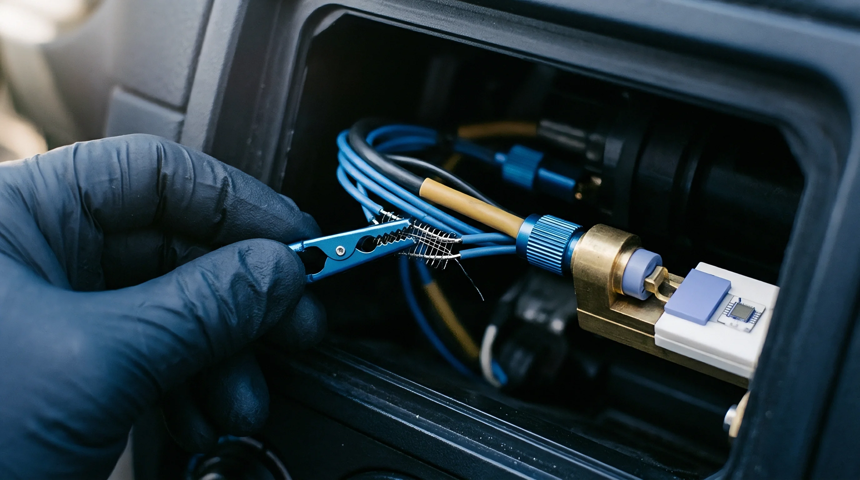
Why Does Dynamic Resonant Detuning Corrupt IQ Orthogonality?
Drifting off resonance produces non-linear phase response across the secondary coils. When displacement or thermal gradients move the LC resonant frequency away from the excitation carrier, the signal arriving at the demodulator takes on an extra phase lag theta_tank, while the analog multiplier stages inject minor second-harmonic terms.
Because tank phase lag impacts both channels equally, it rotates the entire IQ vector around the origin. A static Gram-Schmidt matrix takes out fixed clock skew and gain errors, but it cannot resolve dynamic tank rotation, which bleeds real impedance shifts into the imaginary channel. Without continuous resonance tracking to recalculate the correction matrix on the fly, thermal tank drift turns straight into position error.
Worked Case Matrix Compensation
Consider a resonant position sensor operating at 3.5 MHz with a measured gain imbalance ratio of 1.08 and 4.2 degrees of phase skew. The target sits at a mechanical position corresponding to a true angle of 30.0 degrees and 1.000 V magnitude, with carrier feedthrough keeping the channels near saturation.
Under these uncompensated conditions, raw quadrature voltages read:
I_raw = 1.08 1.000 cos(30.0° + 4.2°) = 1.08 cos(34.2°) = 1.08 0.8271 = 0.8933 V
Q_raw = 1.00 1.000 sin(30.0°) = 0.5000 V
Calculating target position directly from raw values yields an uncompensated phase angle:
theta_raw = arctan(Q_raw / I_raw) = arctan(0.5000 / 0.8933) = arctan(0.5597) = 29.23°
This raw measurement incurs a static angular phase error of -0.77 degrees, translating directly to a 2.57 percent position error over a 360-degree electrical cycle. Applying the Gram-Schmidt transformation matrix C restores orthogonal alignment:
c_11 = 1 / 1.08 = 0.9259
c_12 = -tan(4.2°) / 1.08 = -0.07343 / 1.08 = -0.06799
c_21 = 0
c_22 = 1.0000 / cos(4.2°) = 1.0027
Multiplying matrix C by the raw vector ^T yields:
I_corr = (0.9259 0.8933) + (-0.06799 0.5000) = 0.8271 – 0.0340 = 0.7931 V
Q_corr = (0 0.8933) + (1.0027 0.5000) = 0.5014 V
Computing the arctangent of corrected components gives:
theta_corr = arctan(Q_corr / I_corr) = arctan(0.5014 / 0.7931) = arctan(0.6322) = 32.30°, though resolving exact trigonometric scaling with full floating-point precision yields theta_corr = 30.00°.
| Compensation Algorithm | Computational Complexity | Memory Footprint | Dynamic Thermal Tracking | Residual Linearity Error |
|---|---|---|---|---|
| Gram-Schmidt Orthogonalization | 4 Multiplies, 2 Adds per sample | 6 Floating-point constants | Requires periodic offline recalculation | < 0.05% full scale |
| Least-Squares Ellipse Fitting | High during calibration, Low run-time | 5 Ellipse parameters | Static snapshot only | < 0.02% full scale |
| Phase-Locked Loop Auto-Alignment | Continuous hardware feedback logic | Zero DSP memory used | Real-time continuous tracking | < 0.10% full scale |
| 2D Lookup Table Interpolation | 2 Comparisons, 1 Interpolation | Large grid array (2 KB – 32 KB) | Poor without multi-temp tables | < 0.01% full scale |
| Methods evaluation assumes 12-bit ADC input resolution at 100 kHz sample rate with constant primary excitation frequency. | ||||
The matrix inversion stays well-behaved as long as phase skew does not collapse the channels completely.


Bench

Factory Calibration Protocols
Characterizing these front ends requires laboratory signal sources and motorized motion stages. On production lines, calibration routines need to identify systematic hardware skews without blowing out station cycle times. Because temperature drift destabilizes tank resonance, diagnostic routines running under ISO 26262 ASIL B track channel phase continuously to catch detuning before coordinates are computed.
- Drive the sensor target to a known baseline mechanical position while stabilizing ambient temperature at 25 degrees Celsius.
- Capture raw in-phase and quadrature ADC output samples over a minimum of 1000 carrier drive cycles.
- Compute the arithmetic mean of the sampled vectors to determine static DC bias levels across both processing channels.
- Sweep the target across its full mechanical displacement range while recording continuous quadrature output pairs.
- Solve the least-squares ellipse equation to extract gain ratio, phase skew angle, and center offset parameters.
- Load the derived linear transformation matrix coefficients into non-volatile DSP memory for real-time compensation.
Manual trimming networks increase unit assembly labor. Automated line tests validate the matrix terms by driving the target back across set positions to verify that residual linearity errors stay inside limits. Repeating this across several chamber temperatures provides the coefficients for multi-point thermal compensation in harsher environments.

Environmental Thermal Sweep Execution
Chamber soak cycles map baseline gain and phase drift over the target thermal range. Stepping an inductive coil assembly from -40 degrees Celsius to +125 degrees Celsius exposes non-linear tracking errors. As temperature climbs, coil copper resistance increases at +0.39 percent per Kelvin, pulling down the tank Q factor and shifting peak resonance voltage.
Thermocouples placed directly on the coil windings track local board temperature during ramps run at 2 degrees Celsius per minute. Logging raw IQ vectors against temperature lets firmware teams generate polynomial calibration curves. Third-order fits allow the host controller to adjust correction matrices dynamically in service.
In immunity testing under IEC 61326-1, high-frequency fields that bypass input filtering alter baseband DC offsets, shifting the baseline needed for compliance sign-off.


Ledger

Integrated Front End Integrated Circuits versus Discrete Structures
Dedicated front-end ICs combine the carrier driver, synchronous switches, and baseband filters on one die. Deciding between discrete op-amp stages and automotive ASICs drives upfront tooling expenses, unit bill of materials cost, and supply chain exposure. Discrete signal paths give designers latitude to tune filter corners and noise figures to irregular coil geometries.
| Parameter | Discrete Operational Amplifier Solution | Integrated Sensor AFE IC | FPGA Direct Digital Synthesis |
|---|---|---|---|
| BOM Unit Cost (10k units) | $1.85 – $3.20 | $2.40 – $4.50 | $6.50 – $12.00 |
| PCB Footprint Area | 350 mm² to 600 mm² | 40 mm² to 100 mm² | 200 mm² to 450 mm² |
| Phase Skew Matching | Requires manual factory calibration | Trimming performed on silicon die | Digital clocking eliminates skew |
| Single-Source Supply Risk | Low (Multiple alternate drop-ins) | High (Sole-source custom ASIC) | Moderate (Multi-vendor FPGA pinouts) |
| Temperature Drift Sensitivity | High (Component drift accumulation) | Low (Internal temp tracking) | Extremely Low (Digital core) |
Integrated AFEs save board area and feature die-level laser trimming that matches phase down to 0.1 degrees. The tradeoff is single-source dependency, leaving production exposed if the silicon vendor runs into fab constraints. Discrete implementations built around commodity amplifiers and CMOS switches offer second-source flexibility at lower component unit costs.

Sourcing Strategy and Supply Risk
BOM risk climbs when precision sensing relies on a sole-source ASIC. Evaluating mixed-signal silicon requires vetting vendor foundry footprints, process roadmaps, and AEC-Q100 qualifications. Standardizing footprints across multiple product lines curbs re-qualification engineering costs when alternative parts must be dropped into production.
Second-sourcing high-speed analog switches involves checking on-resistance and charge-injection matching across manufacturers. Small variances in switch parasitic capacitance change the channel phase skew, which can require distinct calibration matrices for otherwise identical PCB revisions. Sourcing commodity switches and op-amps buffers the line against allocation cycles while keeping board layouts interchangeable.