Quantifying Phase Lag Margins in Cascaded Polyphase Decimation Filters for Closed Loop Motion Control
Polyphase decimation stage group delay sums directly across multirate boundaries, stripping phase margin from closed-loop motion regulators at crossover.

Drag
Delta-sigma converters shift quantization noise into the high megahertz range, which requires heavy decimation before field-oriented control algorithms can compute vector voltages. While the rotor’s physical position advances continuously, the current samples reaching the pulse-width modulation generator always lag behind that mechanical angle, creating transport drag. Running an analog-to-digital modulator at twenty megahertz with a decimation factor of two hundred produces a one hundred kilohertz sample stream, but filtering out that modulation noise imposes an envelope delay proportional to the length of the impulse response.
Transport Latency inside Field Oriented Regulators
Vector torque loops execute current conversions within tight microsecond windows, making the stator feedback path the limiting factor for loop crossover frequency. Drive stability drops off quickly once total sensing delay passes ten percent of the sampling period. Because Clarke and Park transforms project phase currents onto rotating direct and quadrature axes, a fundamental-frequency phase lag of just three degrees causes cross-coupling between the flux and torque channels.
During acceleration, the drive ends up injecting demagnetizing current, which heats the magnets and caps peak torque.
At a two kilohertz current loop crossover, a forty microsecond filter delay strips exactly twenty-eight point eight degrees of phase margin.
Every digital processing block between the shunt resistor and the proportional-integral regulator eats into available phase margin. Engineers often blame dead-time or control execution overhead when phase margin runs short, overlooking the decimation filter entirely.
- Delta-sigma modulator sampling delay fixes an initial phase drop equal to half the modulator clock cycle.
- Primary sinc decimation latency contributes the largest raw temporal lag, governed by filter order and decimation ratio.
- Polyphase sub-filter commutation distributes coefficient evaluations across clock phases, adding pipeline register cycles.
- Direct-memory access transfer stalls create deterministic jitter that acts as an unmodeled phase pole.
- Pulse width modulator register shadowing introduces an exact half-carrier update delay before gate signals reach switching transistors.
Left uncorrected, these phase deficits pull down the damping ratio until the system develops audible resonance or drives the power stage into thermal runaway.

Topology
Cascaded decimation splits large downsampling ratios across separate stages, handling bulk decimation first and transition-band shaping downstream. A single-stage sinc filter places wide nulls at multiples of the output rate, but its shallow attenuation between those notches lets high-frequency aliases bleed back into the baseband. Pairing a coarse first-stage sinc filter with a polyphase finite impulse response block improves throughput and sharpens stopband rejection, keeping the passband flat out to the current loop’s Nyquist frequency.
How Do Polyphase Branches Distribute Filtering?
Applying the Noble identities allows the decimation operation to move ahead of the filtering arithmetic. An input commutator routes consecutive high-rate samples into parallel sub-filter branches that run at the lower, decimated clock rate, spreading tap calculations over a longer period. Polyphase restructuring lowers the clock speed needed for hardware multipliers, but it does not shorten the filter’s delay line; the total group delay remains tied directly to the length of the prototype filter.
Polyphase decomposition redistributes arithmetic across sampling intervals without altering the composite filter transfer function.
Multi-rate designs often follow a third-order or fourth-order sinc stage with half-band finite impulse response filters. The sinc stage uses cascaded integrator-comb structures to accumulate and differentiate samples without hardware multipliers, while the half-band filter zeroes out roughly half its coefficients to cut subsequent multiplications in half. This combination steepens the transition band enough to shield current sensing from inverter switching harmonics.
| Filter Topology | Total Decimation | Passband Droop At Two Kilohertz (dB) | Group Delay (Microseconds) | Stopband Rejection (dB) |
|---|---|---|---|---|
| Single-Stage Sinc3 | 128 | -0.03 | 9.6 | -68 |
| Single-Stage Sinc4 | 128 | -0.05 | 12.8 | -92 |
| Sinc3 (Decimate 16) + Half-Band FIR (Decimate 8) | 128 | -0.12 | 21.4 | -86 |
| Sinc4 (Decimate 32) + Polyphase Equiripple (Decimate 4) | 128 | -0.08 | 18.2 | -104 |
| Three-Stage Half-Band Polyphase Cascade | 128 | -0.01 | 34.6 | -112 |
| Group delay measured from first bit arrival to stable output word presentation at controller register. | ||||
Because motor windings integrate the applied voltage, any aliased high-frequency energy folds straight into the baseband feedback channel.


Derivation
Calculating phase erosion starts with the continuous group delay of the discrete z-domain filter. A symmetric, linear-phase finite impulse response filter with N taps clocked at sample frequency Fs introduces a fixed group delay of tau equals N minus one divided by two times Fs. By contrast, non-linear phase designs introduce frequency-dependent delays that distort current harmonics and destabilize sensorless observer algorithms.

Analytical Summation across Multirate Stages
Latency accumulates across every downsampling stage in a cascade. With stage one clocked at modulator frequency Fm using decimation factor M1 and prototype length N1, its group delay is N1 minus one divided by two times Fm seconds. Stage two processes the downsampled rate Fm divided by M1 across an N2-tap filter.
Linear phase filters maintain constant delay. Summing these delays gives the continuous-time equivalent delay tau_sum:
tau_sum = ((N1 – 1) / (2 Fm)) + ((N2 – 1) / (2 (Fm / M1))) + ((N3 – 1) / (2 (Fm / (M1 M2))))
At crossover frequency omega_c, phase lag in radians is simply omega_c multiplied by tau_sum. In degrees, this works out to:
phi_lag_deg = 360 f_c tau_sum
Evaluating phase margin at crossover requires combining the inverter voltage gain, stator impedance, sampling hold, and decimation delay into the open-loop transfer function G_open(s). Factoring in the pure delay term exp(-s tau_sum) from the decimation filter yields the final phase margin PM:
PM = 180 + angle(G_open(j 2 pi f_c)) – (360 f_c tau_sum)
As tau_sum climbs, the added transport delay triggers torque ripple and corrupts velocity estimation, eventually forcing a reduction in crossover frequency to preserve stability at the cost of command tracking bandwidth.
Cascading lower decimation ratios in the first stage preserves phase margin at the expense of higher downstream computational load.
| Loop Crossover Frequency (Hertz) | Unfiltered Plant Phase Margin (Degrees) | Filter Phase Lag (Degrees) | Net Phase Margin (Degrees) | Damping Ratio Zeta |
|---|---|---|---|---|
| 500 | 68.0 | 5.76 | 62.24 | 0.68 |
| 1000 | 62.0 | 11.52 | 50.48 | 0.54 |
| 1500 | 56.0 | 17.28 | 38.72 | 0.41 |
| 2000 | 51.0 | 23.04 | 27.96 | 0.29 |
| 2500 | 47.0 | 28.80 | 18.20 | 0.19 |
| 3000 | 42.0 | 34.56 | 7.44 | 0.08 |
Quantification Protocol for Discrete Feedback Delay
- Identify stage decimation factors and operational clock rates across each cascaded boundary.
- Extract tap lengths for primary comb filters and subsequent polyphase finite impulse response stages.
- Compute stage group delays in seconds using native sampling intervals before scaling by cumulative decimation factors.
- Sum pipeline register delays introduced by multiply-accumulate architectures and bus synchronizers.
- Multiply composite seconds delay by 360 times target loop crossover frequency to isolate phase loss in degrees.
- Subtract calculated phase loss from uncompensated plant phase margin at target crossover to confirm stability limits.
Because transport delay scales directly with filter order, lower-order pre-decimation filters are generally preferable when tuning tight current loops.
Rig
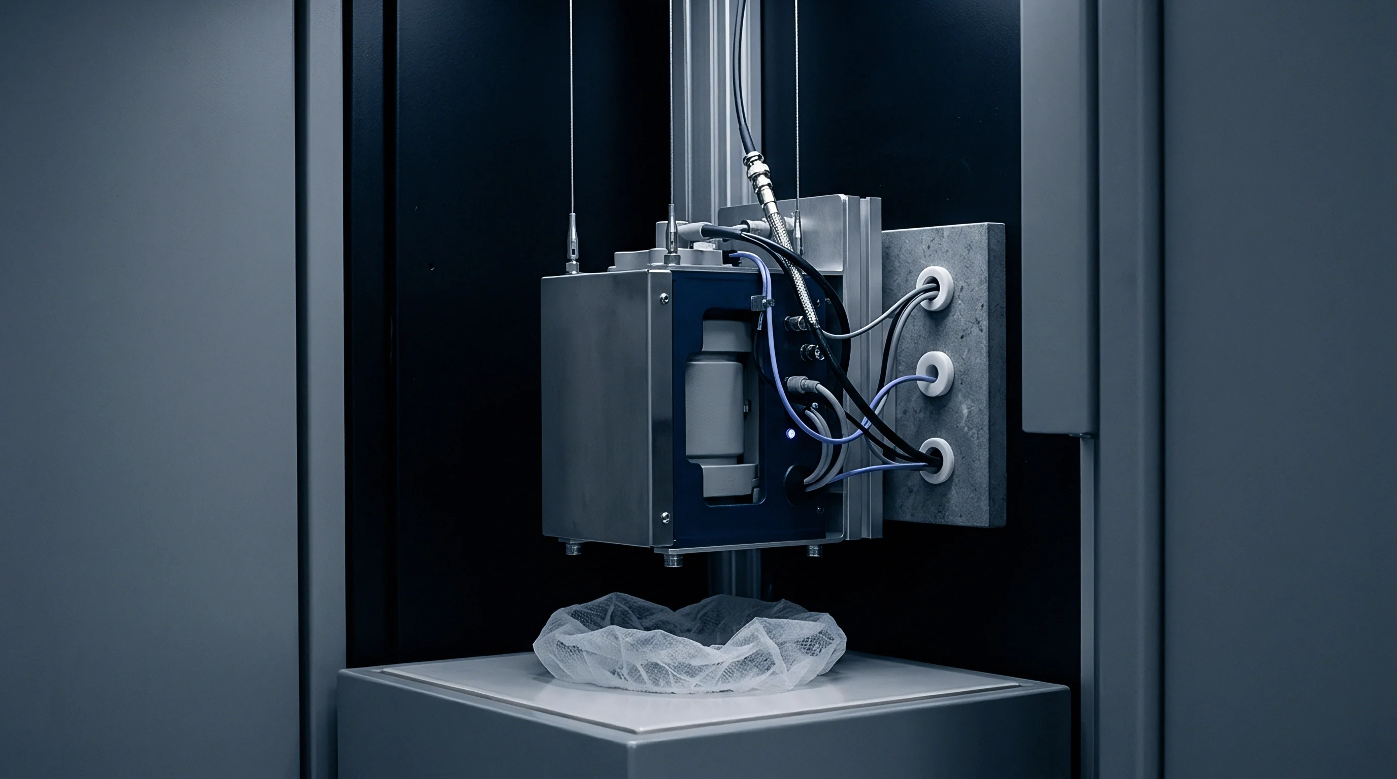
Verifying decimation filter phase margins directly requires swept-sine dynamic signal analysis over the physical sensing hardware. A signal generator drives high-frequency test currents through wideband transconductance amplifiers into low-inductance coaxial shunts, where sampling jitter can distort phase readings. A frequency response analyzer then compares this analog shunt voltage against the reconstructed digital output pulled from drive memory over a high-speed serializer port.
When Do Conversion Delays Exceed Phase Margins?
PWM switching noise coupling into low-voltage delta-sigma bitstreams can easily obscure the filter’s true phase roll-off. At higher modulation indices, common-mode transients induce ground bounce across modulator clock lines. To counter this, the test bench isolates the digital serializer lines with capacitive silicon isolators rated for fifty kilovolts per microsecond common-mode transient immunity.
Phase readings remain dependable only if common-mode current injection stays below five picoamperes across the sweep spectrum.
ISO 13849 safety assessments penalize unmodeled digital filter transport latencies by downgrading the diagnostic coverage rating of the drive.
Sweeping from ten hertz to twenty kilohertz captures the dynamics across the current loop crossover. Reconstructing the decimation register value through a digital-to-analog converter introduces its own zero-order hold lag, which the analysis post-processing mathematically de-embeds to separate filter phase shift from test instrumentation delay.
- Coaxial current shunt selection eliminates inductive phase lead below one hundred kilohertz.
- Differential signal routing prevents pulse width modulation carrier pickup from modulating ADC clock thresholds.
- Synchronous trigger capture aligns swept-sine signal analyzer frames to drive current loop interrupt boundaries.
- Zero-order hold de-embedding subtracts half the digital-to-analog converter update interval from measured phase lag.
Whether dynamic, FPGA-based decimation switching during load transients induces boundary limit cycles remains an unresolved issue in high-speed positioning drives.
Budget
Industrial servo designs distribute a narrow phase margin budget across mechanical compliance, inverter dead-time, and digital processing delay. Machine tool feed axes, for example, typically require at least forty-five degrees of phase margin at a two kilohertz crossover. Allowing decimation filtering to consume more than fifteen degrees compromises positioning stiffness and forces gain derating, which directly slows disturbance rejection.
Hardware Allocation across Silicon Targets
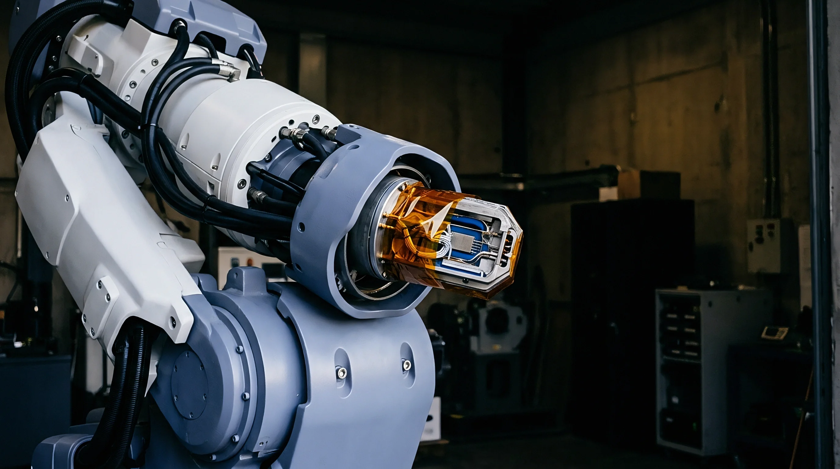
FPGAs and dedicated motion processors impose very different latency penalties when implementing polyphase decimation. Fixed-function silicon embeds sinc decimation into hardware blocks with predictable group delays, but allows no filter customization. FPGAs support tailored polyphase topologies with lower group delay at the expense of logic resources, though pipeline registers added to hit two hundred megahertz timing targets insert discrete transport delays into the feedback path.
| Architecture Scheme | DSP Slices | Look-Up Tables | Pipeline Cycles | Added Group Delay (Nanoseconds) |
|---|---|---|---|---|
| Fully Parallel Polyphase FIR | 32 | 1450 | 2 | 20 |
| Time-Multiplexed Polyphase FIR | 4 | 2890 | 18 | 180 |
| Cascaded Integrator-Comb Hard-Core | 0 | 420 | 1 | 10 |
| Minimum-Phase IIR Infinite Cascade | 8 | 1120 | 6 | 60 |
Minimum-phase infinite impulse response filters sacrifice linear phase response to achieve lower group delay at low frequencies. While this reduces phase lag within the current loop bandwidth, it introduces phase distortion higher up that can compromise velocity observers. Closed-loop drives must continually balance this trade-off between phase linearity and raw transport delay, which is why drive specifications need explicit latency figures for each decimation stage.
Clause 6.3 of IEC 61800-5-2 defines command response tolerances that reclassify drives into derated operating tiers whenever feedback delays push the system past its phase margin limits.