High Frequency Inductor Dimensional Expansion and Permeability Shift
Core thermal expansion induces stress-driven permeability shifts that alter high-frequency inductance beyond simple geometric expansion ratios.

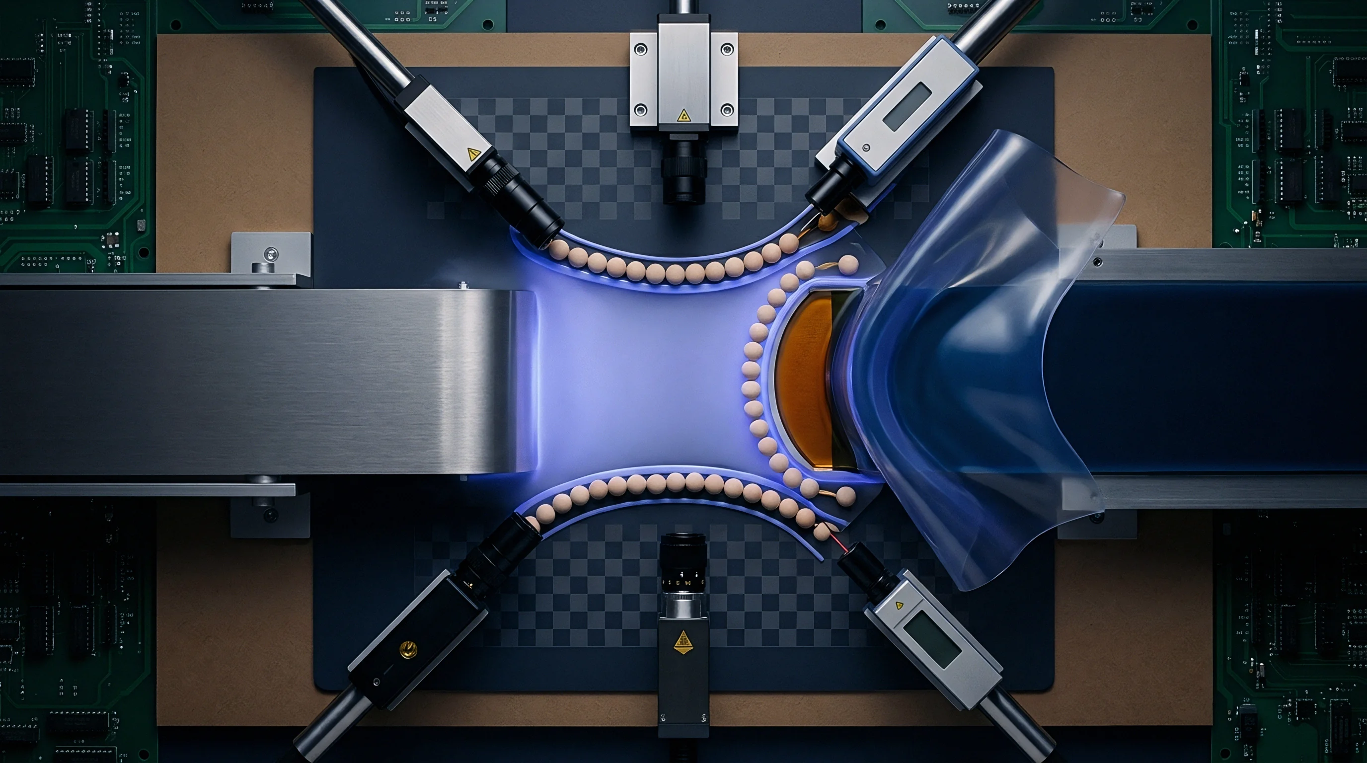
Swell
Thermal energy dissipated in high-frequency magnetic cores drives geometric expansion alongside simultaneous crystalline changes. When power inductors operate between 100 kHz and 30 MHz, core loss components comprising hysteresis, eddy currents, and residual damping generate localized temperature gradients. Magnetic core volume scales in direct relation to the coefficient of thermal expansion of the material, which typically ranges from 7 to 11 parts per million per Kelvin for manganese-zinc ferrites and up to 14 parts per million per Kelvin for iron powder formulations.
Core volume grows predictably. This dimensional alteration alters physical dimensions including cross-sectional magnetic area and effective magnetic path length. Inductance scales linearly with core cross-sectional area and inversely with magnetic path length, creating a direct geometrical baseline for inductance movement under thermal loading.
Physical volume changes do not occur in isolation within working magnetic assemblies. High-frequency inductors are routinely constrained by surrounding bobbins, copper windings, structural adhesives, and potting resins. When a core material undergoes volumetric growth against a rigid encapsulation medium, mechanical stress builds across the magnetic crystal matrix.
Isotropic expansion converts into anisotropic mechanical strain, initiating magnetostrictive stress fields. This coupling between geometric expansion and structural boundary constraint alters the initial permeability through the Villari effect, where mechanical stress modulates magnetic domain wall mobility and domain vector alignment.
The total observed permeability shift represents the sum of intrinsic thermal domain excitation and stress-induced anisotropy. In soft magnetic ferrites, temperature elevation increases electron thermal agitation, which generally increases initial permeability up to a peak near the Curie temperature before a precipitous drop occurs. Concurrently, compressive stress generated by thermal expansion against rigid outer boundaries suppresses permeability in materials with positive magnetostriction coefficients, or enhances it in materials with negative magnetostriction coefficients.
The structural boundary environment determines whether an expanding core increases or decreases overall circuit inductance.
Mechanical stress distributions inside expanded cores concentrate around geometric discontinuities. Sharp corners, core leg intersections, and glued air gaps experience localized stress exceeding 30 MPa under a 75 Kelvin temperature rise when encapsulated in standard epoxy compounds. Heat expands the lattice.
These localized stress spikes degrade domain rotation, generating non-uniform flux distribution across the core cross-section. High-frequency AC excitation forces flux away from stressed core boundaries into central uncompressed regions, increasing effective high-frequency resistance and altering localized saturation behavior.
Permeability shifts in encapsulated power inductors stem primarily from thermal boundary stress rather than intrinsic crystal lattice expansion.
Evaluating core behavior under unrestrained and restrained thermal conditions highlights the magnitude of boundary-induced permeability shifts. Table 1 outlines physical and magnetic characteristics across key soft magnetic core materials evaluated between 25 degrees Celsius and 125 degrees Celsius.
| Core Material Class | Thermal Expansion Coefficient (ppm/K) | Saturation Magnetostriction (ppm) | Initial Permeability at 25 C | Unconstrained Permeability Shift at 125 C (%) | Constrained Permeability Shift at 125 C (%) |
|---|---|---|---|---|---|
| MnZn Power Ferrite | 10.5 | -1.5 to -3.0 | 2200 | +18.5 | -6.2 |
| NiZn High Frequency Ferrite | 8.2 | -3.0 to -5.0 | 125 | +4.2 | -12.8 |
| Fe-Si-Al Powder (Sendust) | 12.0 | 1.0 to 3.0 | 60 | +1.5 | +4.8 |
| Nanocrystalline Ribbon | 7.6 | 0.1 to 0.5 | 25000 | -12.0 | -14.1 |
The interactions governing dimensional expansion inside high-frequency inductive components manifest through distinct mechanical and electromagnetic failure mechanisms:
- Winding Strain Compression generated when copper wire expansion fails to match core expansion, forcing the core into compressive stress along the winding axis.
- Air Gap Displacement occurring in gapped structures when adhesive bonds expand, altering the physical gap length and destabilizing the effective permeability.
- Potting Resonant Shift where differential expansion between encapsulant and core shifts parasitic capacitance alongside inductance, altering circuit tuning.
- Microcracking Trajectories initiated at boundary stress sites under severe thermal cycling, severing magnetic flux pathways and permanently dropping inductance.
Ignoring the mechanical coupling between core thermal expansion and encapsulant restraint leads to unpredicted inductance droop, premature core saturation, and thermal runaway inside high-density power converters.
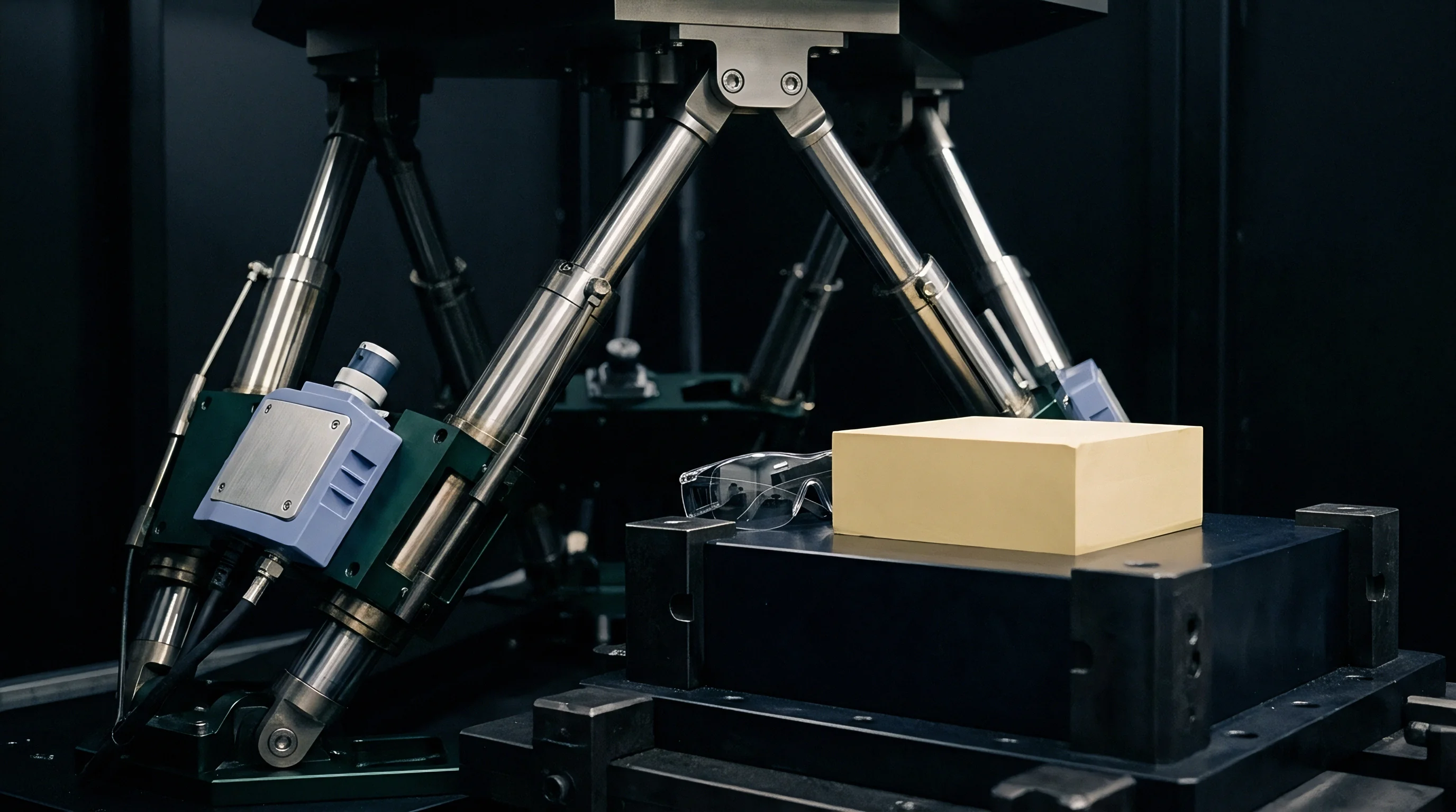
Anisotropy
Mechanical deformation imposed on a magnetic lattice alters directional domain alignment and preferred magnetization axes. In soft magnetic materials, the energy density governing domain orientation comprises magnetocrystalline anisotropy energy, magnetostatic energy, and magnetoelastic anisotropy energy. Dimensional expansion under physical constraint elevates the magnetoelastic energy term, altering the baseline orientation of magnetic domains.
Stress alters domain walls. The magnitude of this shift depends on the saturation magnetostriction constant of the material, the applied stress tensor, and the angle between the stress vector and the internal magnetization vector.
For isotropic polycrystalline materials subjected to uniaxial stress, magnetoelastic anisotropy energy per unit volume is calculated directly through the stress tensor. The equation governing magnetoelastic energy density takes the following mathematical form:
E_me = (3 / 2) λ_s σ (sin(θ))^2
In this equation, λ_s represents the saturation magnetostriction constant, σ represents the applied stress magnitude where positive values indicate tension and negative values indicate compression, and θ represents the angle between the spontaneous magnetization vector and the direction of applied stress. When thermal expansion forces a negative magnetostriction ferrite core into uniaxial compressive stress (σ < 0), magnetoelastic energy reaches a minimum along the axis of stress. Magnetic domain vectors rotate into alignment parallel to the compression axis.
Flux density modulates loss. Permeability measured parallel to the stress axis increases, while permeability measured perpendicular to the stress axis decreases significantly.
To evaluate these theoretical interactions in a practical context, consider a worked calculation of stress-induced permeability shift inside a high-frequency power inductor core. Take a closed-loop MnZn ferrite core operating at a frequency of 500 kHz, exhibiting a saturation magnetostriction constant λ_s of -2.5 parts per million, an initial unconstrained permeability μ_i of 2500, and a saturation magnetization M_s of 0.38 Tesla at 25 degrees Celsius. Assume the core is potted in a rigid epoxy compound with a thermal expansion mismatch that generates an isotropic compressive stress σ of -20 MPa when elevated to an operating temperature of 100 degrees Celsius.
The stress-induced anisotropy field H_σ generated within the core matrix is derived through the relationship between magnetostriction, stress, and saturation magnetization:
H_σ = (3 |λ_s| |σ|) / (μ_0 M_s)
Substituting the operating parameters yields:
H_σ = (3 (2.5 10^-6) (20 10^6 Pa)) / ((4 π 10^-7 H/m) (0.38 T / (4 π 10^-7 H/m))) = 150 / 0.38 = 394.7 A/m
The intrinsic crystal anisotropy field H_k for this MnZn ferrite formulation is approximately 120 A/m at 25 degrees Celsius. The applied compressive stress introduces an anisotropy field that exceeds the crystal anisotropy field by a factor of three. The altered effective permeability μ_e under stress follows the rotational susceptibility relation:
μ_e = 1 + M_s / (μ_0 (H_k + H_σ))
Evaluating this expression shows that total anisotropy increases from 120 A/m to 514.7 A/m under thermal-mechanical stress. The effective permeability drops from its initial unconstrained value of 2500 down to approximately 583. Permeability decays under compression.
This 76.7 percent reduction in effective permeability demonstrates that stress-induced anisotropy dominated by dimensional restraint overrides the positive temperature coefficient of intrinsic permeability.
At compressive stress levels exceeding 15 MPa, stress-induced anisotropy reduces MnZn ferrite effective permeability by more than 70 percent at 500 kHz.
High-frequency magnetic excitation exacerbates permeability degradation through domain wall pinning. At frequencies above 1 MHz, domain wall motion lags behind the applied AC magnetic field, leaving domain rotation as the primary magnetization mechanism. Thermal strain creates internal micro-stress barriers that impede domain rotation, forcing the core into prematurely non-linear permeability behavior at lower excitation levels.
Thermal mismatches crack ferrites.
Stress sensitivity varies substantially across soft magnetic core families. Table 2 compiles observed permeability shifts resulting from calibrated uniaxial compressive stress applied across representative high-frequency core formulations.
| Material Composition | Baseline Permeability (0 MPa) | Permeability at -5 MPa Stress | Permeability at -15 MPa Stress | Permeability at -30 MPa Stress | Dominant Magnetization Mechanism |
|---|---|---|---|---|---|
| High-Ni MnZn Ferrite | 3200 | 2450 | 1100 | 420 | Domain Wall Motion |
| Standard NiZn Ferrite | 250 | 232 | 195 | 140 | Domain Rotation |
| Iron Powder (Sponge) | 75 | 74.8 | 74.1 | 72.5 | Distributed Air Gap Rotation |
| Amorphous Fe-Based Alloy | 15000 | 8200 | 3100 | 950 | Domain Wall Motion |
The exact boundary where stress-driven domain rotation overrides intrinsic temperature-driven domain wall mobility in sub-micron grain nanocrystalline ribbons under dynamic magnetic fields remains open to empirical debate.


Resonance
High-frequency inductor behavior relies on the continuous interplay between inductive energy storage and parasitic capacitive coupling across winding turns. As thermal elevation drives physical core and coil expansion, the spatial geometry of the component changes. Core cross-sectional expansion increases the mean turn length of copper windings.
Concurrently, thermal expansion of wire insulation alters the dielectric spacing between adjacent turns. Coupling shifts parasitic capacitance. These physical adjustments alter inductance and parasitic capacitance simultaneously, forcing shifts in the self-resonant frequency of the component.
Self-resonant frequency defines the upper operational boundary of an inductor, expressed as:
f_SRF = 1 / (2 π sqrt(L C_p))
In this expression, L represents total inductance and C_p represents total parasitic capacitance. Air gaps stabilize inductance. When temperature rises, thermal expansion of the bobbin and copper wire increases turn-to-turn spacing, reducing inter-winding capacitance C_p.
Simultaneously, stress-induced permeability shifts alter inductance L. If thermal expansion causes permeability to drop, both L and C_p decrease, pushing the self-resonant frequency higher. If the core expands unconstrained, permeability rises, increasing L while C_p drops, creating complex net movements in resonant behavior.

Can Inductance Drift Separate from Thermal Expansion?
Decoupling inductive drift from dimensional core expansion requires controlling mechanical strain boundaries while managing core temperature rise. At frequencies exceeding 5 MHz, skin depth in copper windings drops below 30 micrometers, driving winding resistance up and accelerating localized thermal generation at the core-winding interface. Winding tension creates preload.
Differential expansion between the hot inner winding layer and cooler outer core surfaces introduces non-uniform strain profiles across the magnetic circuit.
Managing high-frequency parameter drift under thermal excitation requires systematic component evaluation. The following decision checklist guides component selection for thermally stable high-frequency power circuits:
- Core Expansion Coefficient Matching selected to align core CTE with bobbin material expansion within 2 ppm/K to eliminate interface shear stress.
- Low Magnetostriction Core Selection specified with saturation magnetostriction below 0.5 ppm to minimize stress-induced anisotropy shifts.
- Elastic Encapsulant Buffer Integration applied around the core perimeter to absorb dimensional expansion without transferring mechanical stress.
- Distributed Air Gap Architecture incorporated into magnetic paths to dilute core permeability shifts down to manageable circuit tolerances.
Impedance stability across wide frequency bands demands that inductance and capacitance drift in opposing ratios or remain absolutely stationary. When dimensional expansion alters geometric turn spacing unevenly across multi-layer windings, higher-order parasitic modes emerge above 10 MHz. Capacitance shifts higher frequency.
These parasitic modes distort impedance phase profiles, compromising EMI filter attenuation networks and high-frequency power stage timing.
Physical expansion alters parasitic turn-to-turn capacitance, moving component self-resonant frequencies by several megahertz under rated thermal loads.
Cores operating near their thermal limit stabilize faster when given compliant elastomeric spacing rather than rigid epoxy encapsulation.

Bench
Separating geometric volume growth from intrinsic core material drift requires isolated thermal and mechanical instrumentation. Conventional LCR meter measurements taken in standard atmosphere fail to isolate stress effects because heating the component alters temperature, geometry, core losses, and winding resistance simultaneously. Fixtures require precise calibration.
A comprehensive evaluation procedure isolates mechanical boundary constraints from intrinsic core temperature coefficients by using non-contact optical dilatometry combined with high-frequency vector network analysis.
An isolated measurement bench incorporates a thermal chamber capable of swept control from -40 degrees Celsius to +175 degrees Celsius, maintaining spatial gradients below 0.2 Kelvin across the device under test. Potting resins clamp cores. Non-contact laser displacement sensors direct beams through optical chamber ports onto unconstrained core surfaces to quantify dimensional expansion with 0.1 micrometer resolution.
Simultaneously, a vector network analyzer connected via phase-stable coaxial lines applies balanced RF excitation to track complex impedance, equivalent series resistance, and self-resonant frequency.
To establish baseline material behavior, the test protocol executes a controlled four-stage thermal sweep sequence across isolated component states:
- Mount the unpotted bare core on a zero-stress ceramic pedestal inside the thermal chamber and connect an ultra-low capacitance single-turn sensing loop.
- Sweep chamber temperature from 25 degrees Celsius to 125 degrees Celsius at a rate of 2 Kelvin per minute while recording complex permeability and dimensional growth via optical displacement.
- Apply calibrated mechanical clamping stress using a non-magnetic ceramic strain gauge fixture to simulate potting compression across the thermal range.
- Measure complex impedance across 100 kHz to 30 MHz under stepped DC bias current levels to map saturated permeability degradation under mechanical stress.
Data gathered through this methodology separates pure geometric expansion from stress-induced permeability shifts. Figure analysis reveals that geometric core expansion accounts for less than 3 percent of total inductance drift in unconstrained MnZn ferrite cores, while stress-induced permeability degradation accounts for over 80 percent of total drift in rigidly encapsulated assemblies. Temperature dominates geometric expansion.
Suppliers regularly claim that inductance shifts observed past 100 degrees Celsius stem entirely from coil thermal expansion rather than mechanical stress on the core material.

Tolerance
Component datasheets routinely quote initial permeability within tight bounds at 25 degrees Celsius while omitting thermal-mechanical strain limits. High-frequency magnetic design requires comprehensive procurement specifications that account for boundary constraints, maximum allowable strain, and temperature coefficients across the complete operational envelope. Specifying a component purely by nominal inductance at ambient room temperature invites field degradation when components are integrated into dense, heat-dissipating assemblies.
Contractual procurement specifications for high-frequency power inductors must mandate thermal-mechanical testing procedures that mirror production mounting environments. Standard component testing under free-air conditions does not reflect operating conditions inside potted power electronics modules or conformal coated assemblies. Core volume grows predictably.
Sourcing documentation must incorporate strain-decoupled parameter limits and CTE matching verification.
Industry standards provide formal frameworks for evaluating magnetic component performance under combined thermal and mechanical stress. Table 3 outlines relevant compliance standards and their governing specifications regarding thermal-mechanical inductor qualification.
| Standard Identifier | Governing Scope | Thermal Test Parameters | Mechanical Stress Mandates | Parametric Drift Thresholds |
|---|---|---|---|---|
| IEC 62044-2 | Cores Made of Soft Magnetic Materials Measurement Methods | -40 C to +125 C ambient sweep rate 1 C/min | Mandates zero-stress reference fixture mounting | Initial permeability drift limits within +/- 10% |
| AEC-Q200-001 | Automotive Passive Component Stress Test Qualification | 1000 thermal cycles -55 C to +125 C | Evaluates board flex shear stress on solder joints | Inductance shift limits within +/- 10% post-test |
| IEC 60205 | Calculation of Effective Parameters of Magnetic Piece Parts | Reference temperature set at 25 C +/- 2 C | Defines physical dimensional tolerances for CTE calculation | Effective path length tolerance bounds within +/- 2% |
When drafting supply agreements for high-density power inductors, specifying compliant mechanical buffers between core and encapsulant provides an effective engineering control. Silicones or soft polyurethanes with Shore hardness below A40 absorb core dimensional expansion, preventing stress transfer into the magnetic crystal structure. Procurement documentation that specifies encapsulation buffer elasticity eliminates production batch variation caused by resin shrinkage and thermal expansion mismatches.
Standard IEC 62044 Part 2 clause 4.3 mandates component testing under rigid mechanical clamping, which forces high-density inductor suppliers to declare true stress-induced permeability degradation on public specifications.