Modelling Polymeric Die Attach Stress Relaxation Effects on Accelerometer Bias
Polymeric die attach relaxation shifts accelerometer bias by altering die strain profiles over time, demanding viscoelastic modeling during mechanical layout.

Bond
Mechanical attachment of a microelectromechanical sensor die to its ceramic or leadframe substrate introduces inherent assembly stress. Polymeric materials such as conductive epoxies, non-conductive adhesives, and polyimides cure at elevated processing temperatures, typically between 150°C and 200°C. Cooling down to room temperature generates severe residual stress fields due to coefficient of thermal expansion mismatch between the silicon die, which exhibits a expansion rate around 2.6 ppm/K, and substrates like alumina ceramic at 6.5 ppm/K or copper leadframes at 16.5 ppm/K. Structural polymers operating below or near their glass transition temperature exhibit time-dependent viscoelastic behavior. Polymer chains reorient slowly under residual stress fields, driving localized strain redistribution long after assembly completes.

Thermomechanical Stress Evolution across Curing Cycles
Crosslinking reactions in polymer resins establish a rigid three-dimensional network at peak gelation temperature. Silicon resists plastic strain. As thermal cooling proceeds, differential shrinkage establishes a hydrostatic and shear stress state throughout the adhesive layer.
Normal stresses concentrate along the die edges and corners, while shear stresses maximize at the perimeter boundaries. Post-cure cooling traps non-equilibrium free volume within the glassy polymer matrix, creating a continuous thermodynamic driving force for physical aging and structural relaxation during subsequent storage and operational lifetimes.

Failure Modes Induced by Residual Interface Shear
Unchecked strain transfer across structural interfaces creates physical degradation in precision microstructures. As the polymer chain network relaxes, the changing stress field induces spatial deformation that reaches the active sensing element.
- Asymmetric Die Tilting causes angular misalignment relative to package mounting planes, introducing cross-axis acceleration sensitivity into primary measurement channels.
- Sense Element Warpage alters internal structural symmetry, shifting baseline capacitive gaps in micro-g level transducers.
- Delamination Inception forms localized interfacial micro-voids at high-stress die corners, causing abrupt compliance changes and unrepeatable thermal hysteresis profiles.
- Piezoresistive Strain Coupling shifts baseline electrical resistance in piezoresistive suspension beams, generating long-term offset drift.
Adhesive vendors frequently assert that room-temperature storage moduli below three gigapascals render post-cure stress relaxation negligible in precision sensing applications.


Kinetics
Viscoelastic response in crosslinked polymers follows time-dependent stress dissipation driven by molecular mobility. When held under constant mechanical strain, the internal stress within the material decreases over time. The mathematical description of this relaxation modulus uses a Generalized Maxwell model, represented by a Prony series sum of exponential decay functions across multiple relaxation time constants.
The time-dependent relaxation modulus E(t) under uniaxial strain takes the analytical form:
E(t) = E_infinity + SUM
where E_infinity represents the fully relaxed long-term equilibrium modulus, E_i represents the relaxation strength coefficient of the i-th Maxwell element, and tau_i defines the characteristic relaxation time constant for that specific chain segment mode. Shear stress decays over time.

Time Temperature Superposition and Shift Functions
Polymer molecular motion accelerates at elevated temperatures according to predictable thermal scaling principles. Time-temperature superposition allows short-term stress relaxation measurements taken at elevated thermal steps to form a continuous master curve at a selected reference temperature. The shift factor a_T converts real operating time t into reduced time t_r through the relation t_r = t / a_T.
Above the polymer glass transition temperature, the Williams-Landel-Ferry equation models the temperature dependence of the shift factor:
log10(a_T) = -C1 (T – T_ref) / (C2 + T – T_ref)
where C1 and C2 are empirical material constants, T is the operating temperature, and T_ref is the reference temperature. Below glass transition, thermal activation follows Arrhenius kinetics, where activation energy E_a and universal gas constant R define the shift factor relationship:
ln(a_T) = (E_a / R) (1 / T – 1 / T_ref)
Temperature acceleration scales decay. Viscoelasticity governs polymer relaxation.
| Material Class | Glass Transition Temperature (°C) | Storage Modulus at 25°C (GPa) | Equilibrium Modulus E_infinity (GPa) | Dominant Time Constants (Hours) | CTE Below Tg (ppm/K) |
|---|---|---|---|---|---|
| Silver-Filled Epoxy | 65 to 110 | 6.5 | 0.85 | 12, 140, 1100 | 35 to 45 |
| High-Tg Polyimide | 220 to 280 | 3.8 | 1.20 | 85, 950, 8400 | 20 to 30 |
| Silicone Adhesive | -120 to -50 | 0.015 | 0.002 | 0.1, 1.5, 12 | 180 to 250 |
| Eutectic AuSi Benchmark | 363 (Melting) | 60.0 | 60.00 | Infinite | 13 |
Operating die attach materials well below their glass transition temperature slows stress decay kinetics and stabilizes zero-acceleration bias over extended storage periods.


Deformation
Strain field changes within the structural adhesive pass directly through the silicon die bulk to the active sensing element. Microelectromechanical accelerometers infer external motion by measuring the displacement of a micromachined proof mass suspended by flexural springs. Viscoelastic stress relaxation within the attachment layer modifies the physical shape of the silicon die frame, introducing artificial deflection into the spring-mass suspension.

Which Strain Components Dominate Zero-G Bias Shifts?
Out-of-plane bending curvature and asymmetrical shear gradients across the die plane act as primary drivers. Uniaxial normal strain induces uniform compression, whereas differential shear along the lower die surface forces the top surface into spherical or cylindrical bending. Anchor nodes shift position.
This structural curvature warps the stationary anchor points supporting the suspended sensing microstructures.

Capacitive Sensing Structure Susceptibility
Micromachined proof masses rely on sub-micron physical gaps between interdigital comb fingers. When anchor locations translate due to substrate relaxation, the baseline gap spacing g0 between stationary stator fingers and moveable rotor fingers changes asymmetrical amounts, creating a net capacitive offset voltage.
The acceleration bias error a_bias generated by capacitance imbalance follows the relation:
a_bias = (1 / S) (delta_C / C0)
where S is the structural acceleration sensitivity expressed in picofarads per g, C0 represents baseline resting capacitance, and delta_C is the strain-induced capacitive differential shift. Capacitive gaps shrink. Creep alters structural alignment.
A two-micrometer distortion in die flatness alters capacitive proof mass gaps enough to shift zero-acceleration output by fifteen milligrees at room temperature.
Failing to account for strain transfer relaxation forces system integrators into frequent field recalibrations or expensive factory thermal pre-aging routines.


Computation
Numerical simulation of viscoelastic die attach behavior requires multi-physics finite element modeling that couples solid mechanics with transient material laws. Standard elastic simulations fail to capture time-varying zero-g drift because elastic formulations assume static strain fields for a fixed thermal delta. Incorporating viscoelastic relaxation laws into commercial finite element solvers demands explicit extraction of Prony series parameters from dynamic mechanical analysis test data.

Prony Series Parameter Extraction Workflow
Dynamic mechanical analysis provides empirical storage and loss modulus spectrum data across target operating frequencies. Converting frequency-domain storage modulus E'(omega) and loss modulus E”(omega) into time-domain Prony terms relies on numerical optimization techniques.
- Measure storage modulus and loss modulus across frequency sweeps from 0.1 Hertz to 100 Hertz at isotherm steps spanning minus forty degrees Celsius to one hundred fifty degrees Celsius.
- Apply the Williams-Landel-Ferry shift factor transformation to construct a continuous master curve at the selected reference temperature.
- Fit a five-term Prony series expression to the relaxation modulus curve using non-linear least squares regression optimization.
- Export elastic constants and characteristic relaxation time parameters into the finite element material properties database.
- Map thermal curing profile residual stresses into the meshed micro-sensor assembly as the initial mechanical state.
- Simulate time-dependent displacement fields across sensor anchor nodes under operational thermal profiles over extended time horizons.
- Convert anchor node displacement vectors into capacitive gap changes to predict zero-g bias drift profiles over device operating lifetimes.

Finite Element Boundary Conditions and Mesh Strategy
Accurate stress field representation demands structured solid elements through the thin adhesive thickness. Due to extreme aspect ratios where the die attach thickness ranges from 10 to 30 micrometers while die lateral dimensions span 2 to 6 millimeters, mesh refinement along corner regions requires mapped hex-dominant elements with at least four element layers through the depth. Thermal expansion drives mismatch.
| Prony Term (i) | Relative Modulus (alpha_i) | Relaxation Time tau_i at 25°C (s) | WLF Constant C1 | WLF Constant C2 (°C) | Reference Temp T_ref (°C) |
|---|---|---|---|---|---|
| 1 | 0.215 | 1.2e2 | 14.2 | 51.6 | 25.0 |
| 2 | 0.180 | 8.5e3 | 14.2 | 51.6 | 25.0 |
| 3 | 0.240 | 6.2e4 | 14.2 | 51.6 | 25.0 |
| 4 | 0.165 | 4.1e6 | 14.2 | 51.6 | 25.0 |
| 5 | 0.095 | 3.8e7 | 14.2 | 51.6 | 25.0 |

Worked Example of Stress Relaxation Drift Calculation
Consider a 4.0 mm by 4.0 mm by 0.4 mm silicon sensor die bonded with a 25 micrometer conductive epoxy layer to an alumina ceramic carrier. The post-cure residual shear stress at the die corner equals 45.0 MPa immediately following assembly cooling. Assume operating storage at 85°C for 1,000 hours.
The thermal shift factor a_T at 85°C reduces effective relaxation times by a factor of 120. Modulus decays logarithmically.
Applying the five-term Prony series reveals that after 1,000 hours at 85°C, corner shear stress relaxes from 45.0 MPa down to 29.25 MPa, representing a 35.0 percent net stress drop. Linear strain coupling coefficients derived from structural mechanical modeling establish that each megapascal of shear stress reduction shifts suspended anchor points outward by 0.12 nanometers.
The total physical displacement delta_d of the accelerometer anchor nodes calculates as:
delta_d = (45.0 MPa – 29.25 MPa) 0.12 nm/MPa = 1.89 nm
For a sensing element utilizing a nominal capacitive gap g0 of 1.20 micrometers, a 1.89 nanometer gap displacement induces a fractional capacitive imbalance delta_C / C0 equal to 0.001575, or 0.1575 percent. In a high-sensitivity device possessing a baseline scale factor of 80 milligrees per percent capacitive change, this physical shift translates directly into a zero-g acceleration bias offset:
a_bias = 0.1575 80 mg = 12.6 mg
Bias shifts drift baseline output. Yield drops at elevated temperatures.
Thermal qualification testing under MIL-STD-883 Method 1010 Clause 3.1 mandates temperature cycling to expose stress-driven zero-g drift before assembly release.
Determining whether non-linear viscoelasticity dominates at high operational stress levels remains an active line of inquiry for thin-die MEMS packaging.


Chamber
Empirical validation of stress relaxation models relies on high-precision thermal exposure paired with continuous data acquisition. Standard environmental testing chambers introduce mechanical vibration and thermal fluctuations that obscure sub-milligee bias shifts. Constructing a bench characterization system requires decoupling external physical influences from internal polymer relaxation phenomena.

Test Fixture Design and Environmental Control
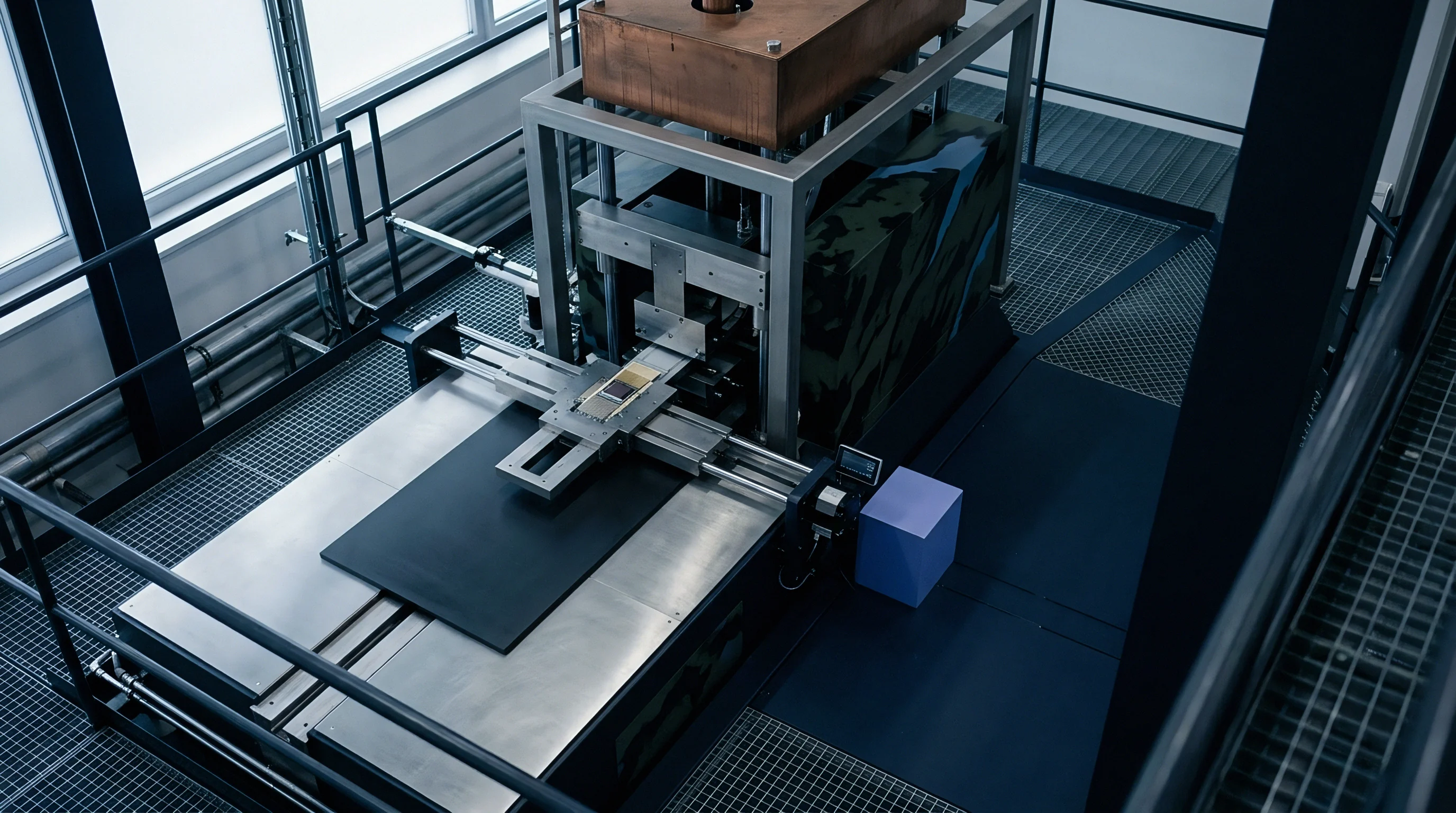
Isothermal testing requires acoustic isolation and thermal stability within hundredths of a degree. Placing test fixtures inside heavy copper thermal-mass enclosures dampened with vibration isolation pads prevents ambient room disturbance from corrupting micro-g output signals.
- Vibration Isolation Mounting blocks external acoustic and mechanical ambient excitation from corrupting sub-milligee bias measurement trends.
- Precision Temperature Regulation maintains environmental chamber stability within five hundredths of a degree Celsius to eliminate thermal sensitivity crosstalk.
- Low-Noise Bridge Excitation stabilizes differential sensor drive voltage across multi-week continuous monitoring trials.
- Automated Zero-G Inversion rotates fixtures by one hundred eighty degrees at fixed intervals to decouple physical sensor drift from measurement channel gain shifts.

Long Term Drift Extraction and Signal Filtering
Raw acceleration readings contain environmental noise that requires algorithmic separation from true viscoelastic offset movement. Continuous thermal exposure over 1,000 to 2,000 hours generates massive time-series datasets. Applying low-pass digital filtering alongside periodic tumble-test recalibration isolates polymer relaxation curves from electronic flicker noise and power rail variations.
Extrapolating long-term bias stability from high-temperature bake data holds only when the exposure temperature remains strictly below the adhesive polymer glass transition point.
Adherence to AEC-Q100 Grade 0 qualification criteria forces component suppliers to demonstrate bias drift boundaries across fifteen hundred thermal cycles.


Sourcing
Selecting die attach chemistry requires balancing mechanical stress mitigation against thermal conductivity, electrical grounding, and high-volume assembly yields. Polymeric adhesives provide compliant stress relief but introduce long-term viscoelastic bias drift. Eutectic bonds eliminate creep.

Polymeric Adhesives versus Eutectic Interface Metallurgy
Eutectic gold-silicon thermocompression bonding eliminates polymer viscoelastic strain decay entirely. Metallic crystal structures exhibit negligible room-temperature creep under micro-scale stress fields. Gold silicon joints stay rigid.
Eutectic processing requires peak temperatures exceeding 380°C, introducing higher initial residual stress that demands thicker silicon dies to prevent physical cracking.
| Attachment Modality | Thermal Conductivity (W/mK) | Post-Cure Stress Level | Viscoelastic Bias Drift Risk | Qualified Wafer Sources | Relative Unit Cost Factor |
|---|---|---|---|---|---|
| Silver Epoxy | 1.5 to 5.0 | Low to Moderate | High | Multiple Global Sources | 1.0x |
| Polyimide Adhesive | 0.3 to 1.2 | Moderate | Moderate | Multiple Global Sources | 1.3x |
| Sintered Ag Paste | 15.0 to 30.0 | Moderate to High | Very Low | Limited Specialty Sources | 2.8x |
| Eutectic AuSi | 150.0 to 200.0 | High | Zero | Specialized Packaging Houses | 4.5x |

Procurement Specification Metrics for Adhesives
Raw material datasheets frequently omit frequency-dependent viscoelastic loss tangent curves required for inertial drift prediction. Sourcing engineers must demand comprehensive rheological characterization dossiers during vendor selection.
- Dynamic Mechanical Properties includes storage modulus, loss modulus, and loss tangent measured across the full operating thermal spectrum.
- Glass Transition Temperature specifies the differential scanning calorimetry peak value with defined heating rates.
- Volatile Outgassing Limits bounds total mass loss and collected volatile condensable material under vacuum exposure standards.
- Isothermal Weight Loss establishes thermal degradation limits during high-temperature wire bonding and sealing steps.
Eutectic die attach eliminates polymer viscoelastic stress relaxation entirely while increasing initial mechanical stress on the silicon die.
Second-sourcing polymeric die attach materials requires cross-qualifying alternate resin formulations using identical thermal cure profiles and glass transition boundaries. Lot-to-lot variations in epoxy oligomer molecular weight distribution alter long-term relaxation kinetics, making raw chemical composition audits essential for maintaining sub-milligee acceleration bias stability across production runs.