Accelerometer Cross Axis Rectification Modeling under Angular Base Motion and Vibration Isolation
Dynamic cross axis rectification models must incorporate quadratic vibration parameters and angular rate coupling terms to eliminate static bias drift under vibration.

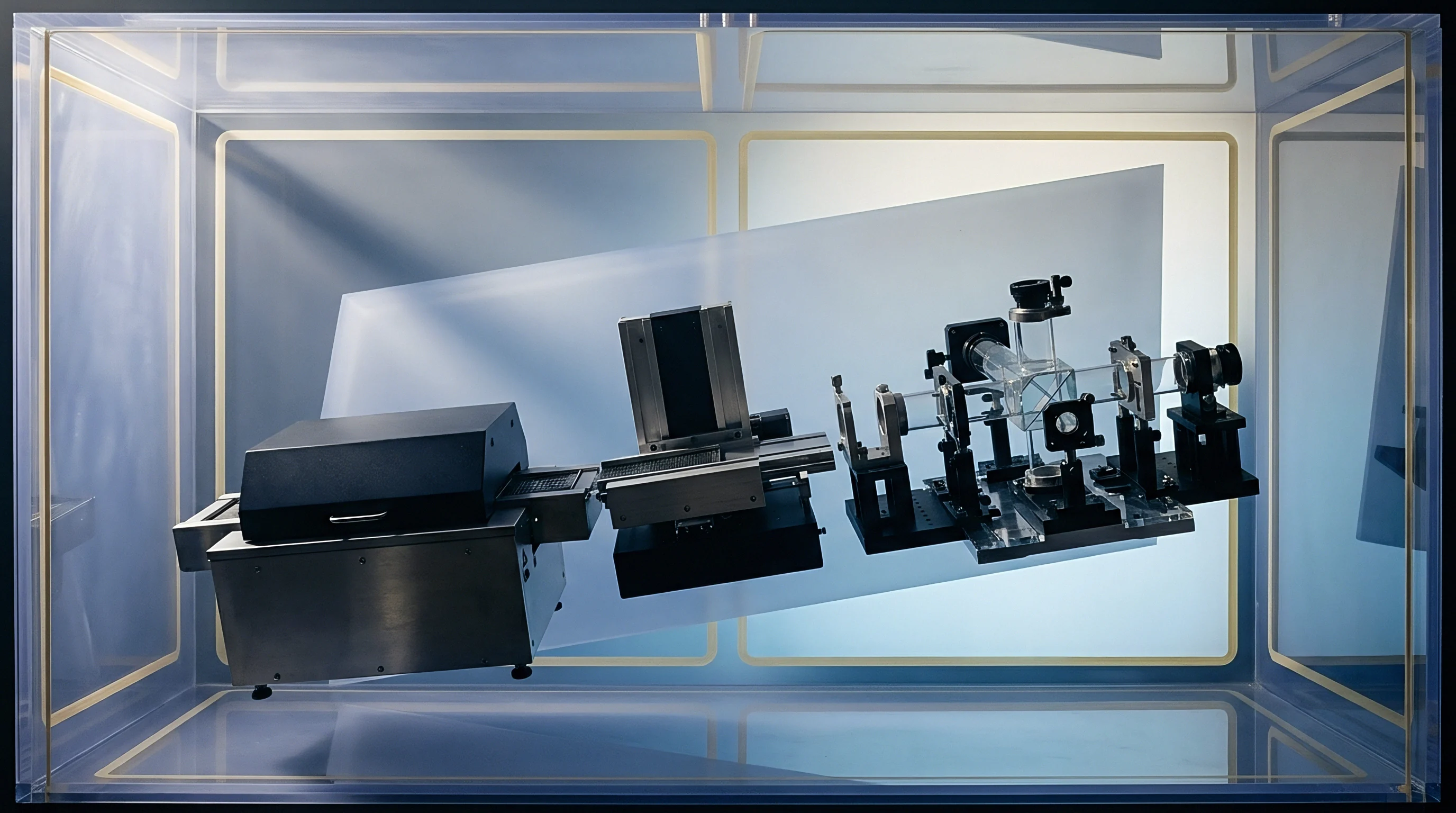
Rectification
Asymmetric mechanical compliance in a proof-mass assembly rectifies zero-mean, high-frequency acceleration into static DC velocity drift. When mounted to vibrating structures, an inertial sensor experiences suspension flexure that differs across orthogonal axes. If high-g oscillation drives the primary sensitive axis while flexing the transverse support structure, the pickoff registers an artificial DC shift.
Static tilt calibrations miss the effect entirely; gravitational positioning cannot reproduce the phase-locked mechanical deformation induced by multi-axis dynamic loads.
Vibration rectification stems principally from two non-linear mechanisms: pendulosity non-linearity and cross-axis alignment flexure. In capacitive micro-electromechanical systems (MEMS), the electrostatic rebalance force scales quadratically with displacement. Under severe vibration, excursions push the proof mass into non-linear operating regions where positive and negative deflections produce unequal changes in capacitance.
Kinematic alignment changes under dynamic bending introduce a secondary error. Orthogonal dynamic loads deflect the sensitive axis by slight angles relative to the package reference frame, causing the sensor to pick up transverse acceleration proportional to instantaneous transverse displacement, with phase lag producing a net DC offset.
MEMS capacitive accelerometers operating under 10 g RMS random vibration between 20 Hz and 2000 Hz generate DC rectification offsets exceeding 1.8 mg when cross-axis compliance asymmetry surpasses 0.5 percent.
Simultaneous dynamic acceleration along both the input and transverse axes yields a rectified output governed by higher-order cross-coupling parameters. These terms are dominated by the cross-axis rectification coefficient, second-order direct rectification, and cross-axis angular rate coupling.
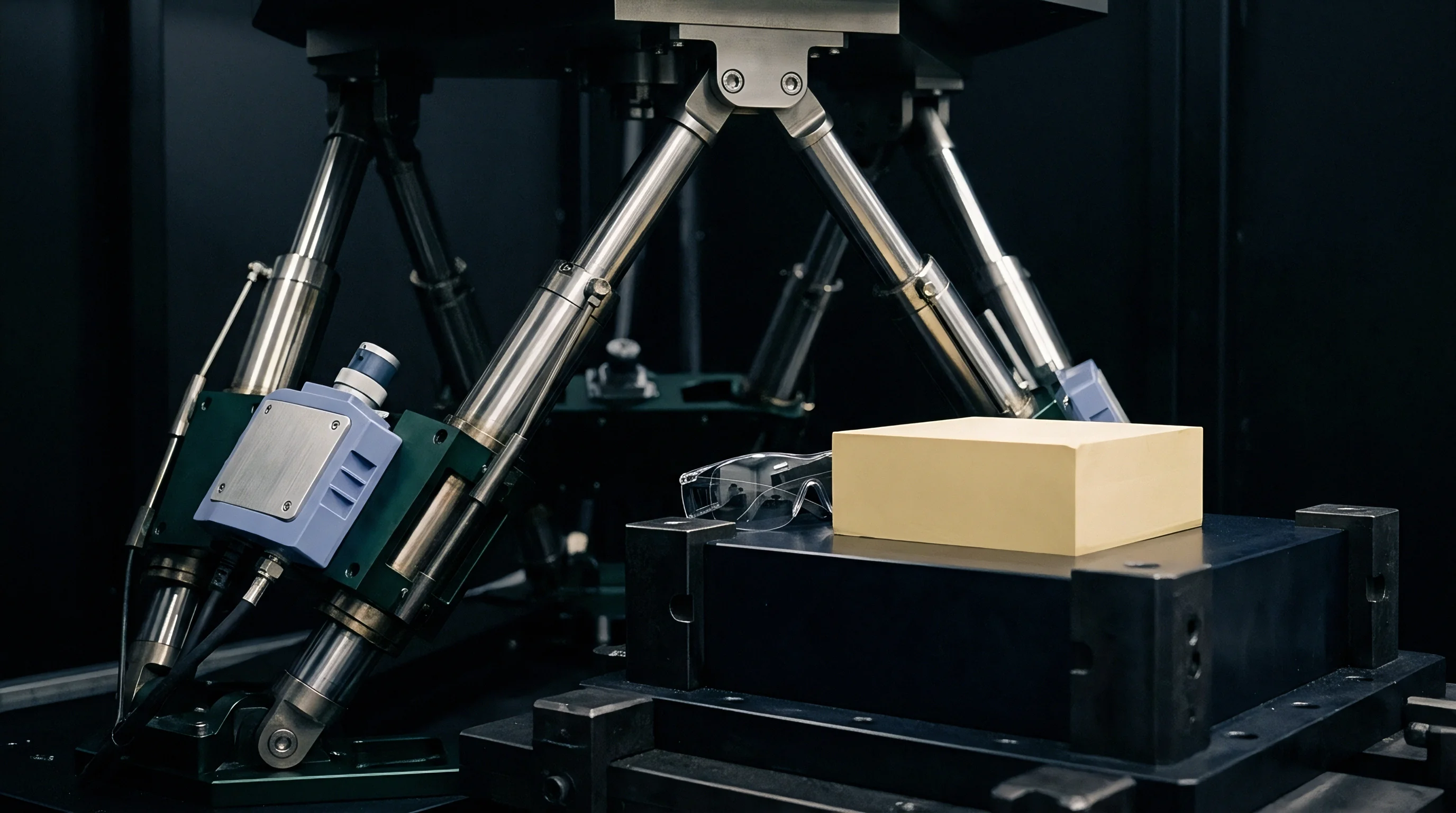
Physical Mechanisms of Asymmetry
Flexures engineered for single-degree-of-freedom translation still have finite torsional and transverse stiffness. Subjected to combined vertical and horizontal vibration, the beam twists as it bends. Transverse displacement narrows the gap of the sensing capacitors on one side and widens it on the other; because electrostatic force and pickoff response vary inversely with the square of electrode separation, the resulting asymmetry fails to cancel out during differential demodulation.
Piezoresistive and quartz elements exhibit their own non-linear mechanisms under dynamic stress. In quartz sensors, where flexural beams operate inside an evacuated cavity, asymmetric squeeze-film damping generates an intensity-dependent DC bias shift. In silicon piezoresistive designs, strain levels exceeding 500 microstrain trigger non-linear stress-strain behavior, driving unequal piezoresistive coefficient shifts across alternating compressive and tensile half-cycles.
Left unmodeled, cross-axis rectification corrupts strapdown navigation solutions through rapid velocity error growth. An error building at several milligrams under ambient vibration rapidly degrades position tracking in unguided dead-reckoning systems, undermining the utility of otherwise high-grade inertial sensors.


Mount
Mechanical isolators attenuate high-frequency inputs, but poor structural geometry can dramatically amplify angular motion. Both elastomeric mounts and wire-rope isolators exhibit non-linear stiffness curves and frequency-dependent damping. If translational vibration excites a package whose center of mass does not coincide with the elastic center of the mounts, the assembly rocks, converting pure linear vibration into angular oscillation.
Transverse base vibration generates angular acceleration around the input axis, sweeping the accelerometer through an arc while translational forces are active. The accompanying angular rates produce centrifugal and tangential acceleration components aligned with the sensitive axis, which the sensor registers as legitimate linear acceleration.
Placing vibration isolators above the center of gravity transforms translational base excitation into rotational rotational modes that severe cross-axis modeling cannot eliminate.
Isolation performance depends heavily on the transfer function across the mount boundary. While damping constrains the resonant peak, high-viscosity elastomeric formulations compromise high-frequency isolation and transmit elevated shear stresses into the housing during broadband random vibration.
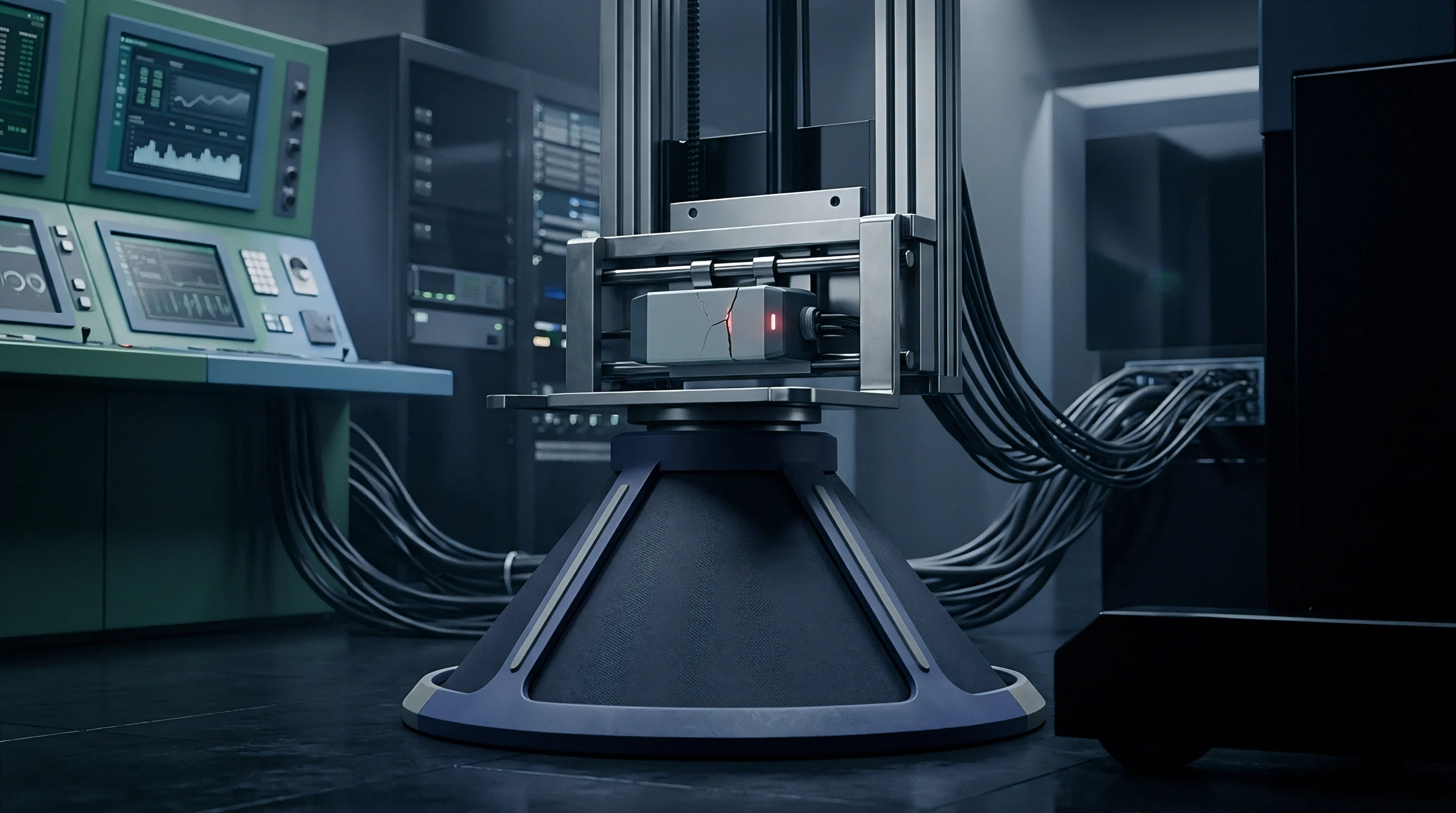
Isolator Transfer Function Derivation Sequence
- Establish the six-degree-of-freedom center of gravity for the fully populated assembly, including housing, signal conditioning boards, and internal shields.
- Map mount elastic centers relative to that center of gravity to isolate coupled translation-to-rotation cross-terms.
- Measure the complex dynamic stiffness tensor of each isolator under operational preload across the operating thermal range from minus 40 degrees Celsius to plus 85 degrees Celsius.
- Calculate natural frequencies for coupled pitch, roll, and yaw rocking modes to ensure structural resonances fall outside the continuous operational frequency bandwidth of the host platform.
- Simulate the isolation transmissibility matrix to quantify angular motion amplification at rocking resonances under dual-axis translational shock inputs.
Temperature shifts alter elastomer durometer, migrating resonant peaks directly into platform excitation bands like rotor pass frequencies or engine firing harmonics. In resonance, cross-axis acceleration can multiply by factors of five to twelve, driving the sensor well into its non-linear rectification regime.
Failing to balance the center of gravity against the isolator elastic center allows translational vibration to produce angular rates that outstrip the dynamic range of downstream processing electronics.

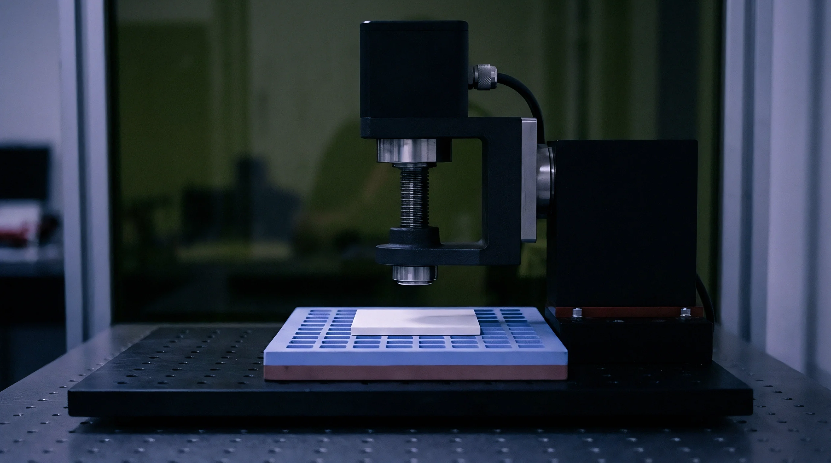
Rotation
Rotational vibration introduces pseudo-coning and sculling profiles that complicate cross-axis modeling. When an inertial package experiences simultaneous, oscillatory angular rates along one axis and translational acceleration along an orthogonal axis, signal integration yields an apparent velocity drift. This sculling offset accumulates even when both inputs average to zero over time.
Angular motion continually reorients the sensitive axis throughout an oscillation cycle. When angular rate components correlate in phase with transverse acceleration, dynamic projections onto the input axis yield a non-zero time average. This geometric coupling scales directly with angular displacement amplitude and transverse acceleration magnitude.

Why Does Angular Base Motion Amplify Cross Axis Misalignment?
Angular motion oscillates the physical frame, sweeping transverse acceleration into periodic alignment with the primary sensing axis. If angular oscillation about a secondary axis occurs at frequency omega, while transverse acceleration along the tertiary axis vibrates at that same frequency omega with a 90-degree phase shift, the rectified projection onto the input axis equals peak angular deflection multiplied by peak linear acceleration and the cosine of the phase angle.
When that phase angle matches the mechanical lag of the isolation mount, the cosine term approaches unity, maximizing the DC bias shift. Static calibration matrices cannot compensate for this behavior because the offset stems from instantaneous angular velocity and dynamic phase lag rather than fixed geometric misalignments.
Evaluating phase-locked coupling under combined rotational and translational loads requires real-time sculling and coning compensation executed at elevated sampling rates. Several core design criteria govern this processing:
- Sampling Bandwidth Ratio requires digitizing at rates at least twenty times higher than the highest isolator rocking resonance, preventing pseudo-sculling terms from aliasing into the navigation passband.
- Phase Synchronicity requires matching phase delays between gyro and accelerometer channels down to sub-millisecond precision.
- Cross Alignment Calibration maps the dynamic misalignment tensor against instantaneous temperature and structural strain fields.
- Quadrature Term Isolation distinguishes kinematic sculling acceleration from proof-mass flexure rectification directly within the navigation processor.
Separating kinematic sculling acceleration from proof-mass rectification remains difficult during broad-band vibration. Because the input kinematics determine whether an apparent bias represents real vehicle trajectory or mechanical distortion, the operational boundary where software algorithms must yield to physical isolation damping is rarely clear-cut.

Formulation
Capturing cross-axis rectification under angular motion requires expanding the traditional linear instrument equation. Where conventional models express acceleration merely as scale factor multiplied by input along with bias and a static misalignment matrix, dynamic environments demand inclusion of second-order terms, third-order coefficients, and kinematic cross-coupling.
The total acceleration measured along the nominal input axis follows the expanded polynomial expression:
a_measured = Bias + (1 + S_x) a_x + S_xy a_y + S_xz a_z + K_xx (a_x)^2 + K_yy (a_y)^2 + K_zz (a_z)^2 + K_xy (a_x a_y) + K_xz (a_x a_z) + K_yz (a_y a_z) + L_x (omega_y a_z – omega_z a_y) + delta_v
Here, S_x accounts for scale factor error, S_xy and S_xz represent linear cross-axis misalignments, K_xx reflects second-order direct non-linearity, and K_yy and K_zz denote transverse second-order rectification coefficients. The cross-product coefficient K_xy models interactions between primary and transverse inputs, while L_x defines the lever-arm distance coupling angular velocities (omega_y, omega_z) directly to transverse acceleration. The term delta_v subsumes wideband noise and unmodeled higher-order dynamics.
ISO 16063 Part 21 qualification clauses require transverse sensitivity measurement across three perpendicular planes to prevent unmodeled quadratic cross-axis terms from voiding strapdown navigation algorithms.
Consider a quartz flexure accelerometer installed in an IMU chassis undergoing dynamic qualification. With the primary sensitive axis aligned with local gravity, a test table introduces 5 g RMS random vibration along the transverse y-axis while driving a 50 Hz sinusoidal angular rate oscillation of 2 radians per second around the z-axis. The device datasheet gives a linear scale factor of 1.2 mA/g, a cross-axis misalignment S_xy of 1.5 milliradians, a transverse rectification coefficient K_yy of 12 micro-g per g-squared, and a cross-coupling parameter K_xy of 8 micro-g per g-squared.
Evaluating the operational bias offset begins with direct linear cross-axis feedthrough. Under a transverse acceleration a_y of 5 g RMS, peak instantaneous feedthrough reaches 7.5 mg; because the vibration is zero-mean and linear resonance is absent, this component integrates to zero net DC bias over time.
The quadratic rectification shift, however, scales with the mean-square acceleration. For a 5 g RMS input, the mean-square value is 25 g-squared. Multiplying by the transverse rectification coefficient K_yy (12 micro-g per g-squared) yields a constant DC bias shift of 300 micro-g, an offset that accumulates monotonically in navigation integrators irrespective of vibration direction.
The angular rate coupling term L_x (omega_y a_z – omega_z a_y) introduces further error. Assuming an angular velocity omega_z of 2 rad/s in phase with transverse acceleration a_y of 5 g (49.05 m/s²), and a lever-arm offset L_x of 0.015 meters, the peak instantaneous coupled acceleration reaches 0.015 (2 × 49.05), producing 1.4715 m/s² (roughly 150 mg). With a 45 degrees phase lag through the isolation mounts, the time-averaged rectified DC bias increases by an additional 106 mg.
| Transduction Principle | Cross-Axis Sensitivity (%) | Vibration Rectification Coefficient (µg/g²) | Non-linear Cross Coupling (µg/g²) | Operational Bandwidth (Hz) |
|---|---|---|---|---|
| Quartz Flexure Accelerometer | 0.05 to 0.15 | 5 to 15 | 2 to 8 | 0 to 500 |
| MEMS Differential Capacitive | 0.50 to 1.50 | 80 to 250 | 30 to 120 | 0 to 1500 |
| Piezoresistive Silicon Beam | 1.00 to 2.50 | 150 to 450 | 50 to 200 | 0 to 3000 |
| Ceramic Piezoelectric Ring | 1.50 to 3.50 | 300 to 800 | 100 to 500 | 10 to 10000 |
| Data collected at 23 degrees Celsius under 10 g RMS broad-band white noise acceleration (20 Hz to 2000 Hz) per ISO 16063 test specifications. | ||||
Combining the linear feedthrough, quadratic rectification, and kinematic angular coupling results in a total rectified DC error of 300.106 mg. Over a ten-minute unguided profile, an uncorrected offset of that scale induces position drift exceeding 53 meters.

Bench
Empirical validation of cross-axis rectification requires test equipment capable of isolating angular motion from translational input. Single-axis electrodynamic shakers cannot quantify quadratic cross-coupling because they cannot apply orthogonal vectors simultaneously; characterization requires multi-axis shakers or dual-axis rate tables mounted to high-frequency horizontal slip tables.
Isolating internal transduction non-linearities from structural resonances requires mounting the unit in an ultra-rigid beryllium fixture. Designing the fixture so its first structural resonance lies above 4000 Hz prevents test-stand compliance from contaminating rectification measurements across the operating band.
Dual-axis rate tables with integrated high-frequency electrodynamic shakers reveal non-linear rectification terms that static tilt calibrations omit completely.
Calibration protocols typically pair single-frequency sine sweeps with shaped random vibration profiles, monitoring DC bias shifts continuously. Reversing package orientation by 180 degrees on the shaker head separates local gravity components from actual dynamic rectification offsets.
| Isolator Material Class | Durometer (Shore A) | Resonant Peak Transmissibility (Q) | Angular Motion Amplification Factor | Thermal Shift (-40C to +85C) |
|---|---|---|---|---|
| High-Damping Silicone Elastomer | 40 to 50 | 2.5 to 3.5 | 1.2 to 1.8x | 15 percent stiffness change |
| Fluorosilicone Rubber Compound | 55 to 65 | 4.0 to 6.0 | 2.1 to 3.0x | 35 percent stiffness change |
| Stainless Steel Wire Mesh Pad | Not Applicable | 3.0 to 4.5 | 1.5 to 2.2x | 5 percent stiffness change |
| Viscoelastic Polymer Matrix | 30 to 45 | 1.8 to 2.5 | 1.1 to 1.5x | 60 percent stiffness change |
Automated test benches record output stability across defined thermal plateaus during qualification. Thermal gradients across the sensor housing present particular risk: differential thermal expansion distorts capacitive sensing gaps, shifting rectification coefficients while dynamic testing is underway.
Industry qualification standards establish baseline test profiles for evaluating dynamic cross-coupling under multi-axis environments.
Qualification dossiers must demonstrate compliance with ISO 16063 Part 21 methods for measuring transverse vibration sensitivity across the full operating spectrum.

Sourcing
Procuring inertial sensors for harsh vibration and angular environments requires contractual specifications that address non-linear cross-axis behavior directly. Commercial datasheets routinely emphasize single-axis noise density and linear scale factor while omitting second-order vibration rectification data. Request for Quotation (RFQ) packages must therefore require vendors to guarantee rectification limits under defined multi-axis excitation.
Sensor architecture determines inherent sensitivity to rectification. Quartz flexure units achieve low VRE figures but carry high unit costs and limited shock survival limits. Capacitive silicon MEMS devices provide rugged shock tolerance at substantially lower unit cost, but exhibit higher cross-axis non-linearities that require intensive algorithmic correction downstream.
| Sensor Architecture Tier | Unit Cost Range (USD) | Typical VRE Rating (µg/g²) | Primary Failure Mode | Supplier Pool Count |
|---|---|---|---|---|
| Navigation-Grade Quartz Flexure | 3000 to 8000 | 2 to 10 | Flexure fracture under extreme shock | 3 worldwide sources |
| Tactical-Grade MEMS Capacitive | 400 to 1200 | 50 to 150 | Capacitive pickoff saturation | 8 worldwide sources |
| Industrial MEMS Capacitive | 30 to 150 | 200 to 800 | Severe cross-axis DC bias shift | 25+ worldwide sources |
| High-g Piezoresistive Beam | 150 to 500 | 100 to 400 | Signal-to-noise floor degradation | 6 worldwide sources |
Procurement specifications for high-vibration applications require several core engineering deliverables:
- Vibration Rectification Coefficient Limits define maximum permissible DC bias shift in micro-g per g-squared under broadband random vibration from 20 Hz to 2000 Hz.
- Axis Misalignment Matrix Calibration provides serialized misalignment matrices mapped at temperature intervals of 15 degrees Celsius.
- High-Frequency Phase Response Profile establishes phase matching across X, Y, and Z axes within 0.5 degrees up to the mechanical isolation cutoff frequency.
- Production Acceptance Test Records verify 100 percent screening of production units on dual-axis vibration fixtures to flag assembly-level variations.
Severe dynamic environments reduce manufacturing yields as capacitive pickoffs saturate under peak transient loads. Sourcing decisions for strapdown navigation ultimately weigh initial component costs against the extensive engineering effort required to model and compensate for elevated rectification errors in lower-tier silicon.