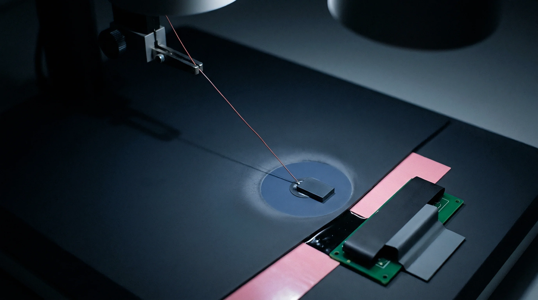
Calibration Boundary
An offset limit defines the allowable deviation at the absolute floor of a measurement range for sensitive electromechanical transducers. Zero scale error tolerance establishes the maximum permissible discrepancy between a true null input and the reported output signal. Designers calculate this value by subtracting the measured baseline from the theoretical origin point before applying any gain factors.
Instruments exceeding this margin exhibit signal bias that propagates through the entire range. Calibration certificates document this deviation as a primary indicator of component stability.
Sensor Linearity
Electronic components maintain performance specifications across a prescribed input spectrum by anchoring the lower bound against ground. The zero scale error tolerance provides a static constraint to ensure that ambient noise or internal component drift remains within predefined voltage or current limits at the point of zero excitation. Engineers verify this limit by grounding the input leads and monitoring the output for unintended residual signal energy.
Output Stability
Thermal fluctuations alter the internal impedance of bridge circuits and create variable offsets. This behavior requires periodic reset cycles to maintain the zero scale error tolerance at the specified level. Manufacturers design temperature compensation networks to mitigate these physical shifts.
Frequent shifts beyond the threshold signify structural fatigue or degradation of the sensing element.
Maintenance Protocol
Technicians assess the integrity of the measurement chain by comparing the observed baseline against factory benchmarks. Proper grounding and shielded cabling reduce the electromagnetic interference that inflates these null readings during active operation. Regular verification procedures confirm that the physical components remain within their designed operating parameters.
Accurate null mapping ensures consistent performance regardless of external load conditions.