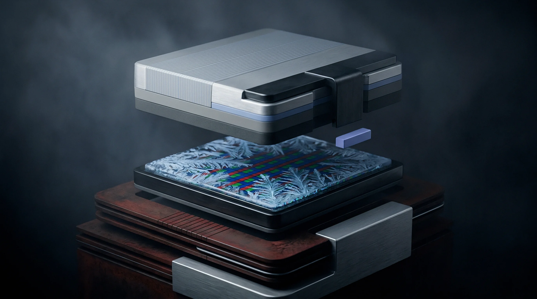
Bias Drift
Unintended bias offset output change occurs in angular rate sensors when zero rotational motion is present across changing environmental conditions. Quantified in degrees per hour or degrees per second per degree Celsius, zero rate shift reflects uncompensated quadrature errors, package stress shifts, and thermal gradients acting on sensing microstructures. The parameter governs navigation bias accuracy and orientation tracking stability in MEMS gyroscopes, losing governing relevance when internal closed-loop force-rebalance circuits or active auto-zeroing routines override static bias states.
Thermal Distortion
Thermal deformation alters drive and sense comb finger spacings unevenly, inducing parasitic capacitive imbalances. Asymmetric stress propagation from package solder joints shifts mechanical resonance frequencies, creating false rotation signals.
Demodulation Error
Phase shifts in sense channel demodulation electronics leak drive-frequency quadrature signals directly into rate output channels. Dynamic thermal gradients across the sensor die generate transient zero rate shifts that static compensation matrices cannot eliminate. Advanced ASIC architectures implement continuous phase tracking to minimize demodulation-induced bias shifts.
Compensation Floor
Characterization procedures log zero rate outputs during multi-axis thermal cycling and mechanical shock testing. Sourcing specifications set maximum allowable bias instability and temperature hysteresis limits. Acoustic noise coupling near resonant drive frequencies degrades zero rate stability severely.