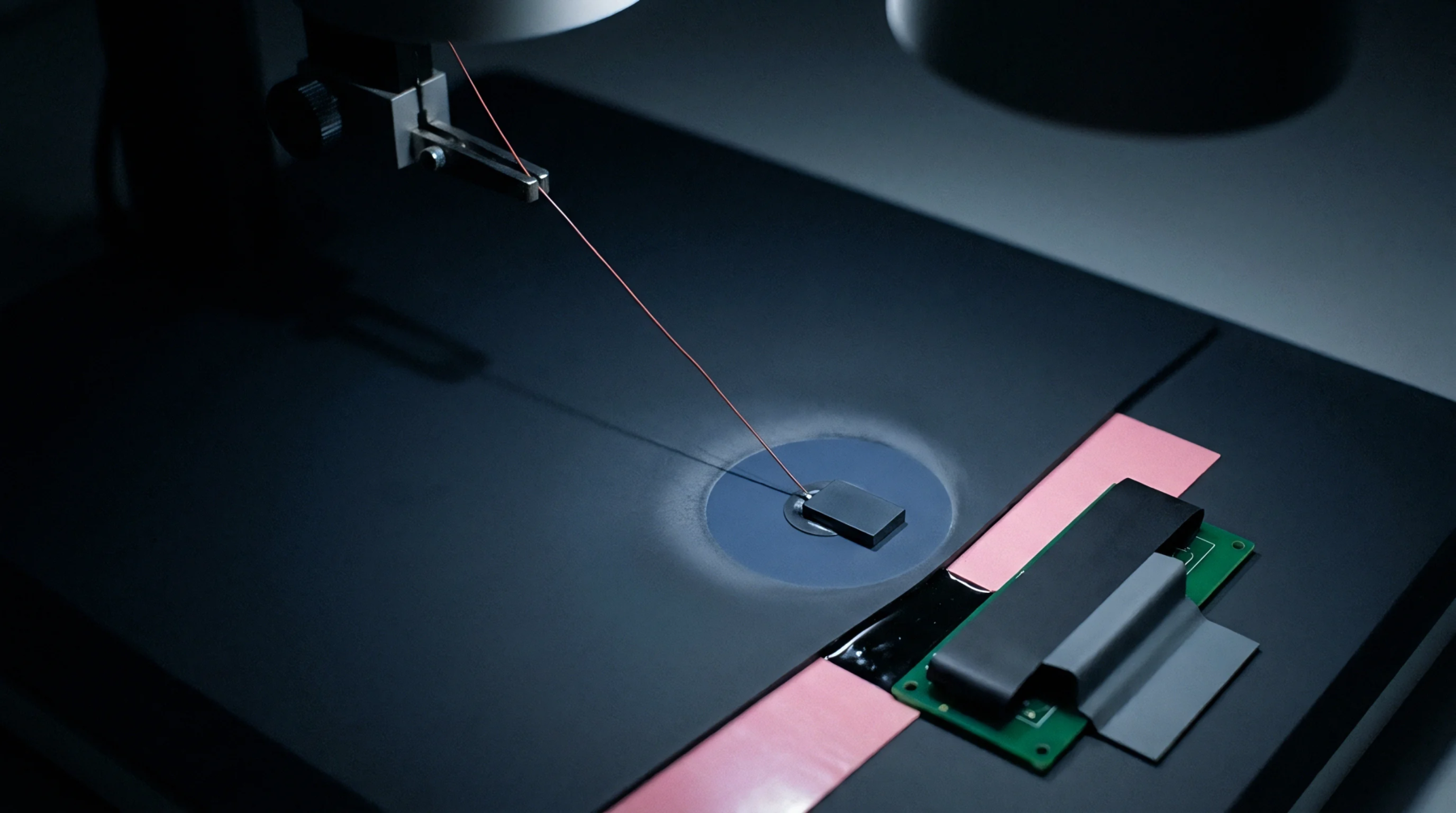
Metrological Verification
Resistance measurement provides the primary methodology for strain gage calibration through the application of known physical loads to a test specimen. Technicians perform this procedure by installing the component on a calibrated load cell or beam that possesses traceability to national standards. Verification requires the application of multiple force increments across the full design range to establish a transfer function.
Linearity deviations between the output of the gage and the reference standard define the measurement error. This error calculation depends on the bridge completion circuit and the excitation voltage stability during testing.
Calibration Procedure
Mechanical displacement of the substrate generates a change in resistance which represents the strain gage calibration coefficient. Operators attach the gage to a material with a known elastic modulus to ensure that applied stress translates into predictable microstrain. Excitation hardware must supply a constant voltage or current to maintain consistency while the gage undergoes physical deformation.
Signal conditioning equipment then translates the resistance change into a voltage output that links to the original reference load. Every measurement cycle records the hysteresis observed during both loading and unloading phases.
Systemic Drift
Environmental stability dictates the accuracy of strain gage calibration because temperature gradients alter the resistance of the metal foil or semiconductor elements. Thermal expansion differences between the gage and the carrier material introduce parasitic signals that mask the intended mechanical strain. Laboratory settings control these variables to prevent non-mechanical resistance fluctuations from corrupting the result.
Humidity and mechanical aging also introduce long term shifts that degrade the fidelity of the transfer function. Shielding of lead wires against electromagnetic interference remains a requirement for achieving low noise performance during high resolution sensing.
Tolerance Compliance
National standards define the acceptable variance allowed for strain gage calibration based on the target application and the sensor accuracy class. Manufacturers specify the gage factor and its tolerance at room temperature. Verification protocols identify if the unit remains within its rated uncertainty after the bonding process completes.
Any shift outside the stated band necessitates a correction factor or outright rejection of the component. The integrity of the final measurement chain rests entirely on the consistency of the initial laboratory verification.