Physical Footprint
Semiconductor packaging relies on standardized geometries to secure silicon dies onto printed circuit boards, and an SOIC package applies a gull-wing lead configuration across a small outline integrated circuit. Body widths typically measure four millimetres or seven point five millimetres depending on pin count, while lead pitch remains fixed at one point two seven millimetres. Thermal dissipation depends directly on copper leadframe thickness and mold compound thermal conductivity, which together determine junction-to-ambient thermal resistance values.
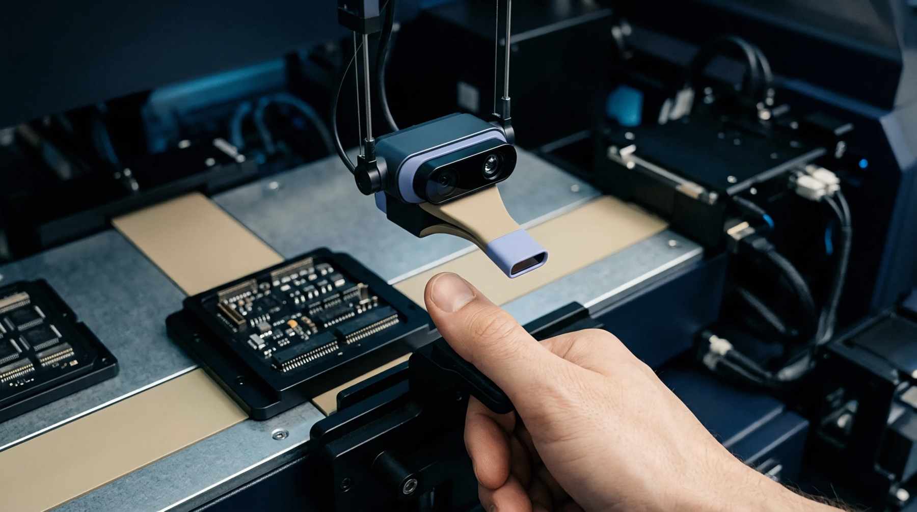
Automated pick-and-place machines align these gull-wing leads onto solder paste deposits before reflow ovens melt the alloy to form permanent mechanical and electrical joints.
Assembly Tolerance
Surface mount manufacturing requires strict dimensional control over coplanarity because gull-wing leads extend outward from the molded body. Coplanarity deviation exceeding zero point one millimetres prevents proper contact with individual solder pads during thermal reflow, leading to open circuits. Optical inspection systems measure lead tip height relative to a seating plane before board insertion occurs, ensuring that automated placement equipment maintains positional repeatability.
Stencil thickness variations and solder paste volume tolerances dictate fillet formation during convection reflow, whereas insufficient paste volume creates starved joints prone to mechanical fatigue under thermal cycling.
Thermal Derating
Semiconductor junction temperature increases during electrical operation, requiring precise calculation of maximum power dissipation limits. Maximum allowable ambient temperature depends on thermal resistance coefficients specified by semiconductor manufacturers for each specific die size. Exceeding these thermal limits degrades wire bonds inside the molded cavity and accelerates semiconductor aging mechanisms.
Heat dissipation occurs primarily through the copper leadframe rather than the plastic encapsulation material, meaning board-level copper trace area heavily influences continuous power handling capacity.
Mechanical Stress
Board flexing and thermal expansion mismatches induce mechanical shear forces along soldered gull-wing joints over prolonged operational lifespans. Ceramic printed circuit boards and standard FR4 fibreglass substrates exhibit different coefficients of thermal expansion, creating cyclic fatigue at the outermost pins of a gull-wing component. Conformal coatings mitigate environmental moisture ingress while adding structural rigidity that dampens vibrational energy transferred from industrial enclosures to internal wire bonds.
Ultimate reliability is achieved when substrate copper weight and package body mass reach equilibrium under operational temperature extremes.