Failure Classification
Solder joint embrittlement represents a primary cause of electrical open circuits in electronic assemblies subjected to drop testing. In lead-free solder connections, intermetallic compound fracture occurs when a crack propagates through the thin, brittle alloy layer that forms between the copper pad and the solder bulk.
Growth Mechanism
Solid-state diffusion during storage or operation at elevated temperatures causes the intermetallic layer to grow thicker over time, increasing its susceptibility to failure. As the thickness of the alloy layer exceeds a few micrometers, the internal stresses rise, and the fracture toughness of the interface drops. The presence of voiding, caused by impurities or incomplete wetting during the soldering process, creates stress concentrators that accelerate the initiation of cracks under mechanical load.
Test Verification
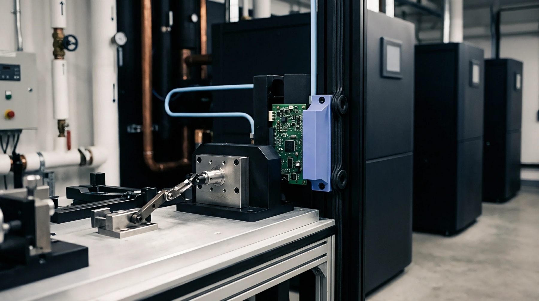
Mechanical shear tests and high-speed pull tests are the standard tools used to evaluate the strength of the solder interface and categorize the fracture mode. In a high-speed ball pull test, a hydraulic actuator applies a rapid tensile load to the solder sphere, forcing the joint to break and allowing the operator to inspect the fracture surface. Post-test examination under a scanning electron microscope reveals whether the failure was ductile, occurring within the solder bulk, or brittle, which corresponds to the intermetallic interface.
Prevention Standard
Board designers reduce the risk of this brittle separation by specifying surface finishes like electroless nickel immersion gold or organic solderability preservatives. The nickel layer acts as a diffusion barrier, slowing down the reaction between copper and tin and limiting the intermetallic growth to a thin, stable alloy. Controlling the reflow profile by limiting the time above liquidus temperature also prevents the formation of an excessively thick and fragile interfacial layer.