Mathematical Modeling
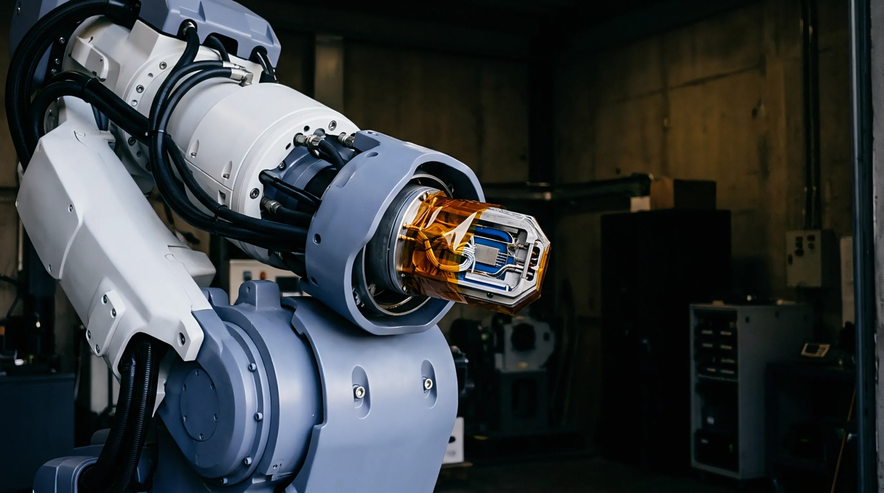
Calibration procedures for multi-axis force and torque transducers establish the transformation matrix required to convert raw voltage outputs into orthogonal force and moment components. Through 6-dof calibration, a systematic series of known loads is applied along three translation and three rotation axes to characterize the sensor output. This procedure resolves the crosstalk coefficients that describe how a force along one axis produces a false signal on another channel.
Reference Standard
Traceable reference machines supply the multi-axis forces used to determine the sensitivity matrix of the device under test. These calibration systems employ orthogonal actuator assemblies to execute independent loads on each axis. In-situ verification must be performed at specified angular intervals to verify that the angular alignment of the applied force vectors remains within tight tolerances.
Error Source
Geometric misalignments between the calibration fixture and the transducer axes produce systematic measurement bias. If the loading vector is tilted by even a fraction of a degree, the resulting shear force is registered on the adjacent channels. This geometric offset constitutes the primary source of calibration uncertainty in multi-axis sensor systems.
Operational Boundary
Thermal drift restricts the temperature range over which the calculated calibration matrix remains valid. Beyond these thermal limits, the expansion of the internal strain gauge substrate alters the structural sensitivity, making a new calibration necessary.