Package Inductance Effects on Precision Reference Stability
Package inductance degrades precision reference output stability by forming parasitic LC resonances that erode phase margin and high-frequency power rejection.


Lead
Physical packages house voltage reference die while introducing finite conductor impedance between internal silicon pads and external printed circuits. Bond wires, leadframe traces, and package pins contain self-inductance that alters high-frequency electrical performance. Precision reference ICs maintain output stability through internal feedback amplifiers, but external packaging parasitics change the open-loop transfer function at megahertz frequencies.
Leadframe geometry dictates pin inductance.
Plastic small-outline integrated circuit packages introduce significant pin series inductance due to long leadframes and internal wire bonds. A standard SOIC-8 leadframe exhibits self-inductance between 2.0 nH and 4.5 nH per pin, depending on whether the pin connects to an end corner or a center pad. Quad flat no-lead packages reduce this value to 0.4 nH through 1.2 nH by eliminating gull-wing leads and shrinking internal bond wire lengths.
Ceramic leadless chip carrier structures drop parasitic inductance below 0.5 nH per pin, providing superior high-frequency isolation for precision bandgap circuit blocks.
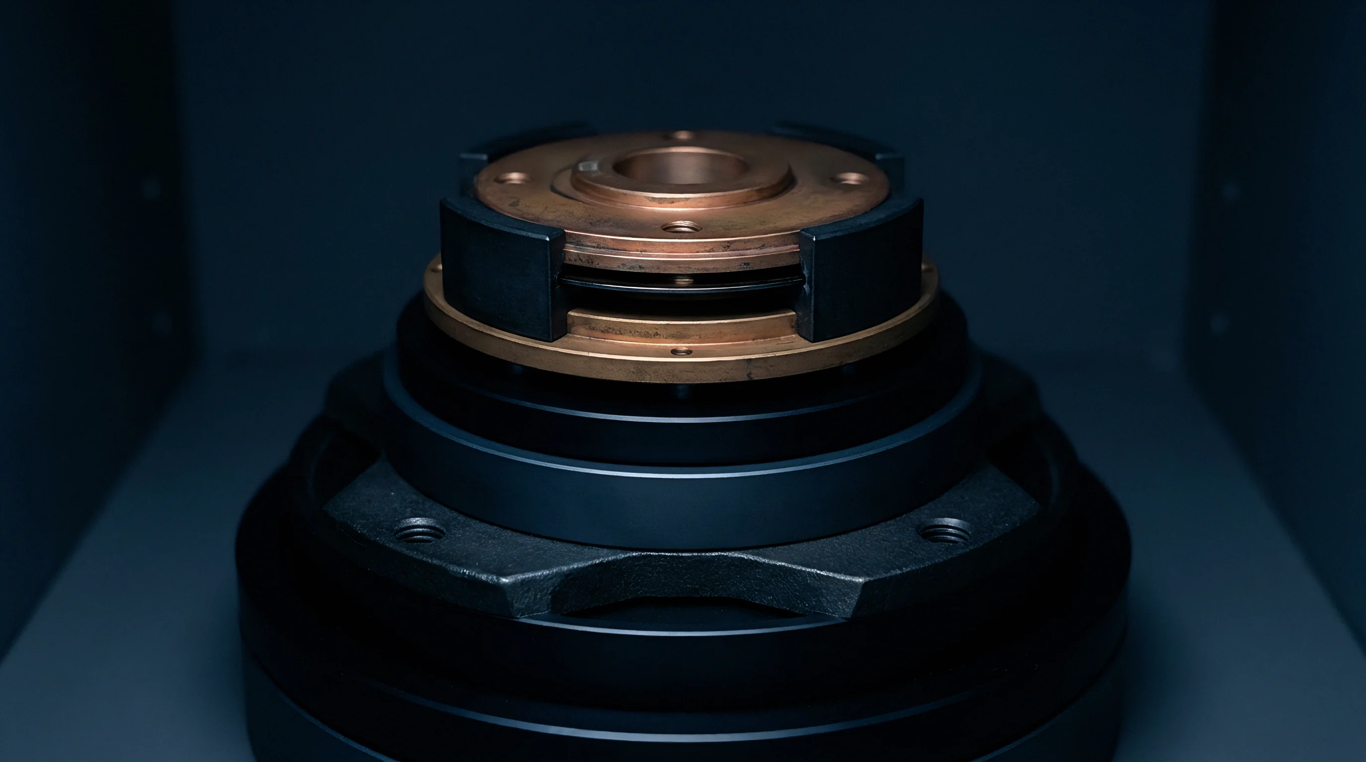
Bond Wire Geometries and Leadframe Parasitics
Conductors connecting internal silicon pads to external package pins introduce stray reactive components. A standard 25-micrometer gold bond wire contributes roughly 1.0 nH of self-inductance per millimeter of length. Die attach pad placement inside the package envelope forces outer pins to utilize longer bond wires, creating asymmetry in parasitic impedance profiles across output, ground, and supply terminals.
Silicon performance degrades under packaging stress.
Mutual inductance between adjacent pins introduces crosstalk within the IC housing. High-speed switching transients on adjacent control lines induce unwanted voltage spikes on precision reference output pins through magnetic coupling. Standard package lead spacing of 1.27 mm creates mutual inductance values ranging from 0.5 nH to 1.5 nH between neighboring conductors, whereas fine-pitch packages with 0.5 mm spacing increase capacitive coupling while altering inductive loop paths.
| Package Format | Pin Count | Lead Self-Inductance (nH) | Mutual Inductance (nH) | Thermal Stress (ppm/°C) | Relative Cost Ratio |
|---|---|---|---|---|---|
| SOIC-8 | 8 | 3.2 ± 0.8 | 0.9 ± 0.2 | 8.5 ± 1.1 | 1.00 |
| MSOP-8 | 8 | 2.1 ± 0.4 | 0.6 ± 0.1 | 10.2 ± 1.4 | 1.15 |
| DFN-8 (3×3 mm) | 8 | 0.8 ± 0.2 | 0.3 ± 0.1 | 12.4 ± 1.8 | 1.30 |
| LCC-20 (Ceramic) | 20 | 0.4 ± 0.1 | 0.15 ± 0.05 | 2.1 ± 0.3 | 4.50 |
| WLCSP-6 | 6 | 0.15 ± 0.05 | 0.08 ± 0.02 | 14.1 ± 2.2 | 1.85 |
Mechanical stress interact with package electrical profiles over time and temperature. Differential thermal expansion between plastic molding compounds, copper alloy leadframes, and silicon dies induces micro-scale mechanical displacement. Board flex translates directly into offset shift.
This mechanical strain shifts die stress states, altering bandgap reference offsets while thermal cycling degrades solder joint interfaces, increasing series inductance over product lifetimes.
Ignoring package lead inductance during initial circuit simulation leads to unexpected high-frequency oscillations and degraded transient response when prototyping on physical circuit boards.


Bounce
Transient supply currents flowing through package pin self-inductance induce localized voltage shifts across internal reference ground nodes. Bond wires act as lumped inductive elements. When external loads draw step currents from a precision reference, the internal amplifier responds by driving output stage transistors.
The rate of current change across ground pin inductance yields a proportional voltage deviation, shifting the internal die substrate potential relative to external circuit ground planes.
Ground bounce corrupts the internal voltage reference core by modulating the base-emitter junctions of sensitive bandgap transistors. A load step of 10 mA with a rise time of 5 ns through a 3.0 nH ground lead produces a transient voltage deviation of 60 mV across internal ground structures. This impulse bypasses low-frequency feedback control loops, forcing output voltage recovery times to extend beyond parameters specified in linear steady-state datasheets.
Decoupling capacitors rated at 100 nF show an impedance null at 15 MHz when paired with 3.2 nH package lead self-inductance.

High-Frequency Power Supply Rejection Roll-Off
Power supply rejection ratios degrade at high frequencies as package conductors decouple internal nodes from external filter networks. High frequency ripple bypasses internal feedback controls. Standard precision voltage references achieve power supply rejection exceeding 100 dB at direct current, but performance drops steeply above 10 kHz.
Package inductance combined with internal junction capacitances forms high-Q parasitic filter poles that pass high-frequency supply ripple directly into reference output stages.
Supply pin self-inductance limits the attenuation capability of external bypass capacitors. Placing a high-quality ceramic bypass capacitor on a printed circuit board fails to mitigate high-frequency supply noise if internal package bond wire inductance dominates total loop impedance above 1 MHz. Supply noise at 10 MHz enters the reference die directly, modulating output voltage accuracy through parasitic collector-base capacitance in output power devices.
Inductive effects create critical stability vulnerabilities in high-precision measurement systems:
- Ground Shift Modulation alters the internal bandgap bias current by shifting internal substrate reference potential relative to external ground planes during fast current steps.
- Parasitic LC Tank Resonance forms high-Q impedance spikes that amplify power supply ripple at frequencies matching the tank natural resonance.
- Output Amplifier Phase Loss reduces loop phase margin when package pin self-inductance interacts with external capacitive load branches.
- Substrate Current Injection drives transient charge into neighboring precision nodes when ground bounce forward-biases internal isolation diodes.

Quantifying LC Resonant Peaks in Decoupling Loops
Calculations governing parasitic tank networks reveal sharp impedance spikes across standard bypass configurations. Consider a precision voltage reference housed in a plastic SOIC-8 package with a ground pin self-inductance of 3.2 nH. The application circuit connects a 100 nF surface-mount ceramic bypass capacitor to the reference output pin.
The external capacitor exhibits an equivalent series inductance of 0.8 nH and an equivalent series resistance of 0.05 ohms. The total loop inductance combines package lead inductance and capacitor parasitics, yielding a net inductance of 4.0 nH.
The natural resonant frequency of this network arises from the series combination of loop inductance and bypass capacitance:
Resonant Frequency = 1 / (2 PI SQRT(L_total C_out))
Substituting 4.0 nH for loop inductance and 100 nF for output capacitance identifies a distinct resonant frequency at 7.96 MHz. The characteristic impedance of this tank circuit evaluates to 0.20 ohms, calculated as the square root of loop inductance divided by capacitance. The quality factor of the resulting resonance measures 4.0, derived by dividing characteristic impedance by net series resistance.
At 7.96 MHz, the parasitic network creates an impedance peak of 0.80 ohms instead of an ideal low-impedance bypass node. Fast load steps excite high frequency ringing. A transient current change at this exact frequency causes sustained ringing on the reference output line, degrading 16-bit and 24-bit analog-to-digital converter performance during conversion cycles.
Component manufacturers frequently attribute high-frequency output instability to improper board layout choices rather than admitting that package bond wire inductance limits internal amplifier phase margin under capacitive loads.


Resonance
Amplifier loop compensation inside precision references relies on stable load impedances across all operating frequencies. Internal feedback architectures monitor output voltage to maintain part-per-million accuracy over temperature. Package self-inductance introduces a zero-pole pair into the amplifier feedback loop, shifting loop crossover points and eroding phase margin.
Uncompensated loops cause continuous parasitic oscillation.
Capacitive loading on reference outputs forms a complex load network when combined with package lead inductance. Small ceramic capacitors placed near package pins decrease high-frequency impedance, but lead inductance separates the internal feedback node from the external physical load. This separation causes internal amplifier output nodes to see an inductive load at high frequencies, turning positive phase shifts into localized loop instability.
IPC-7351 land pattern tolerances that expand pad area by twenty percent double the stray pin capacitance to the internal ground plane.

Which Layout Guard Bands Prevent High Frequency Reference Oscillations?
Isolation traces and ground fill clearances shield sensitive feedback loops from adjacent digital activity. Ground loops corrupt low noise measurements. Board designers maintain explicit physical clearances around precision reference package pins to control parasitic capacitance and minimize inductive loop enclosure areas.
Trace inductance degrades supply rejection performance.
Extending ground planes directly beneath reference packages forms localized parasitic capacitances that alter lead resonance characteristics. Microstrip geometries beneath SOIC and DFN packages introduce 0.2 pF to 1.5 pF of capacitance between package leads and reference ground planes. High-frequency noise currents flow through these stray capacitive paths, re-entering package leads and bypassing external decoupling components.
| Topology Configuration | Total Loop Inductance (nH) | Capacitance Network (µF) | Peak Impedance (Ω) | Q Factor | Settling Time to 0.001% (ns) |
|---|---|---|---|---|---|
| Direct 100 nF Ceramic | 4.0 | 0.1 | 0.80 | 4.0 | 450 |
| Parallel 100 nF + 10 µF Ceramic | 3.5 | 10.1 | 0.45 | 2.1 | 220 |
| Damped 100 nF + 1 Ω Series R | 4.0 | 0.1 | 1.05 | 0.2 | 65 |
| RC Parallel (100 nF || 4.7 µF + 0.5 Ω) | 2.8 | 4.8 | 0.25 | 0.5 | 85 |
Validating high-frequency stability across precision reference package options demands structured laboratory measurement steps:
- Connect a high-bandwidth active differential probe directly across reference package output and ground pins using sub-millimeter tip adapters.
- Inject a 10 mA step current with a sub-nanosecond edge rate into the reference output node using a fast pulse generator and high-frequency coupling network.
- Capture the output voltage response on a high-bandwidth digital oscilloscope to measure peak overshoot amplitude and initial ringing frequency.
- Calculate total loop inductance by matching observed transient ringing frequencies against known external load capacitance values.
- Sweep power supply ripple frequencies from 10 kHz to 50 MHz using a network analyzer to plot high-frequency power supply rejection ratio roll-off profiles.
- Compare measured output impedance profiles against open-loop amplifier phase margin predictions to confirm stable operation boundaries.
What structural modifications inside integrated circuit packaging can eliminate internal bond wire self-inductance without introducing severe thermal mechanical stress on precision silicon dies?

Topology
Printed circuit board trace geometries alter the total loop inductance connected to reference pins. Minimizing physical conductor lengths between package pins and local bypass capacitors reduces high-frequency impedance peaks. Placing decoupling components on the bottom side of printed circuit boards introduces via inductances of approximately 0.5 nH to 1.2 nH per via, eroding the benefit of low-inductance package selection.
Star ground configurations concentrate return paths at a single low-impedance node, isolating precision analog ground connections from heavy switching currents. Connecting reference ground pins directly to large copper fills using multiple short vias drops parasitic ground loop inductance. Routing reference output lines parallel to ground planes maintains consistent transmission line impedance, shielding low-level reference signals from external electromagnetic interference.
Routing the force and sense traces inside an isolated inner layer protects precision feedback nodes against capacitive coupling from fast digital clock lines.

Kelvin Connection Placement across Package Pins
Force and sense connections eliminate voltage drops across trace resistances when tied directly at the device pads. High-precision reference packages provide separate force and sense pins for both output and ground paths. Tying force and sense traces together at the load instead of at package pins incorporates trace self-inductance inside the internal feedback loop, adjusting output drive to compensate for dynamic lead losses.
Inductive coupling between force and sense lines creates secondary feedback loops that compromise high-frequency stability. Routing force and sense traces side-by-side over long distances introduces mutual inductance, allowing high-frequency current spikes on force lines to couple into high-impedance sense inputs. Maintaining physical clearance between force and sense conductors until they terminate at the load prevents parasitic feedback paths.
Selecting package forms for precision references involves specific layout constraints and performance boundaries:
- Hermetic Ceramic Packages yield minimum parasitic inductance while isolating internal silicon from board flex stress in severe operating environments.
- Small Outline Gull-Wing Packages offer simple visual solder inspection access but introduce high lead self-inductance that degrades high-frequency power supply rejection.
- Flat No-Lead Packages minimize package pin inductance and overall footprint area while demanding tight stencil process controls during surface mount assembly.
- Wafer Level Chip Scale Formats eliminate leadframe parasitics entirely but transfer mechanical substrate stress directly to the underlying silicon die.
Procurement documentation for high-reliability systems must specify maximum allowable package pin self-inductance alongside standard direct-current voltage offset parameters to guarantee cross-vendor part substitution stability.


Economics
Selecting package formats requires balancing mechanical reliability, electrical performance, and high-volume manufacturing costs. Silicon die designs often ship across five distinct package options, ranging from inexpensive SOT-23 housings to premium ceramic leadless chip carriers. A single precision bandgap die priced at one dollar in standard plastic packaging commands five to ten times higher prices when packaged inside hermetic ceramic enclosures designed for harsh aerospace environments.
Assembly line yield factors strongly influence the true landed cost of low-inductance packaging options. Ultra-small wafer-level chip scale packages and fine-pitch QFN packages reduce lead inductance to sub-nanohenry levels, but their tiny pad pitches demand strict stencil aperture controls and automated optical inspection steps. Solder bridging, tombstoning, and voiding under bottom-terminated reference pads drive manufacturing scrap rates higher, offsetting initial component savings accrued from smaller package dimensions.

Commercial Cost Ladders across Packaging Variants
Silicon dies packaged in standard plastic enclosures deliver lower unit expenses compared to ceramic hermetic housings. Automated high-speed wire bonding lines process thousands of SOIC and MSOP leadframes per hour, achieving high assembly line yields. Transitioning to ceramic LCC housings requires specialized assembly tooling, hermetic gold-tin lid sealing operations, and individual fine-leak helium testing procedures that add substantial fixed manufacturing costs per unit.
| Package Variant | MOQ (Units) | Assembly Yield (%) | Unit Cost ($) | Land Pattern Footprint (mm²) | Target Application |
|---|---|---|---|---|---|
| SOT-23-5 | 3,000 | 99.8 ± 0.1 | 0.65 | 9.0 | Consumer Electronics |
| SOIC-8 | 2,500 | 99.9 ± 0.05 | 1.10 | 31.0 | Industrial Process Control |
| DFN-8 (3×3 mm) | 3,000 | 99.2 ± 0.2 | 1.45 | 9.0 | Compact Instrumentation |
| WLCSP-6 | 5,000 | 98.5 ± 0.4 | 1.80 | 2.2 | Portable Test Equipment |
| LCC-20 (Ceramic) | 250 | 99.5 ± 0.15 | 12.50 | 78.0 | Aerospace Defense Systems |
High-reliability military and space applications pay significant price premiums for ceramic packaging options because hermetic sealing prevents moisture ingress over decade-long service lives. Plastic encapsulated devices absorb atmospheric moisture over time, creating mechanical package swelling that degrades reference output stability through piezoresistive stress effects. Ceramic packages isolate internal thermal stress.
Ceramic construction stabilizes die stress and minimizes pin inductance, providing predictable high-frequency performance despite higher initial unit costs.
Shielding adds measurable board footprint costs. Yield losses rise with sub-millimeter pin pitches. Product engineering teams evaluating reference IC options calculate total cost of ownership by adding component purchase price, printed circuit board real estate costs, thermal management additions, and expected assembly scrap rates.
Wafer-level chip scale packaging presents the lowest stray inductance and smallest footprint, yet demands rigorous thermal cycling verification to validate solder joint fatigue limits on thick glass-epoxy circuit boards.