Phase Dependent Vibration Rectification in Multi Axis MEMS Accelerometers
Phase-dependent vibration rectification shifts multi-axis MEMS DC bias when orthogonal dynamic displacements intermodulate through non-linear tethers and combs.


Clamp
Bolted circuit assemblies subjected to high-frequency structural excitation exhibit acceleration biases that simple single-axis laboratory calibrations fail to predict. When an industrial gearbox or rocket motor casing shakes an instrumented enclosure at 2.4 kHz with 15 g root-mean-square amplitude, three-axis capacitive silicon transducers register steady-state output offsets up to 85 milli-g along axes experiencing zero net translational velocity. The physical origin rests in the mechanical assembly housing the silicon die.
Fastening torque across mounting lugs introduces mechanical stress gradients across the sensor package substrate. Leadframe and ceramic carrier packages warp under non-uniform retention loads, transferring micro-strain directly to the silicon die attach boundary. This uneven boundary condition tilts the internal proof mass suspension beams away from planar orthogonality.
Silicon tethers deflect sideways. The tilt permits high-amplitude dynamic displacement along the primary excitation vector to displace the sensing mass along nominal cross-axes.
Torque applied to an aluminum mounting flange above 1.8 Newton-meters induces 42 micro-strain package deformation that increases orthogonal rectification by 18 milli-g per g squared at 1.5 kilohertz.
Dynamic forces rarely arrive aligned with the orthogonal axes defined by silicon micromachining masks. Rotary machinery generates elliptical or orbital displacement patterns where orthogonal stress waves travel through the enclosure baseplate with fixed time delays. When high-frequency mechanical waves sweep through the assembly, the instantaneous package flexure modulates internal anchor positions.
Package stress shifts resonant frequencies.

Mechanical Preload and Package Asymmetry
Retention hardware sets the baseline boundary stiffness for the entire transducer die paddle. Uneven bolt torque deforms the sensor package, bending the internal anchor posts that suspend the proof mass. An anchor post rotated by merely 0.05 degrees couples out-of-plane z-axis displacement into the in-plane x-axis comb finger gap.
When high-frequency vibration excites the package along the z-axis, the tilted anchor forces the proof mass to travel diagonally.
The resulting trajectory introduces an asymmetrical displacement profile between differential capacitor finger pairs. Symmetrical finger pairs produce equal and opposite capacitive variations whose quadratic terms cancel during differential signal processing. Anchor rotation breaks this geometric symmetry, leaving unbalanced second-order displacement terms uncancelled.
The uncancelled term rectifies the alternating mechanical cycle into a persistent directional DC bias voltage.

Cross-Axis Vibration Energy Vectors
Industrial machinery generates orbital acceleration vectors governed by shaft rotation harmonics and structural resonances. A bearing housing vibrates simultaneously along horizontal and vertical coordinates, with the two vibration components separated by a phase delay determined by structural stiffness and damping paths. The combined trajectory traces an ellipse in space rather than a straight line.
Conventional sensor qualification procedures isolate each coordinate axis on a single-axis shaker table, evaluating cross-axis sensitivity through sequential orthogonal exposures. This evaluation missed the dynamic interaction of simultaneous multi-axis excitation. When out-of-phase dynamic motions occur concurrently along the principal sensing axis and the cross-axis, the time-varying cross-axis displacement modulates the primary axis spring constant at the exact vibration frequency.
This concurrent modulation generates a non-zero time-average force that shifts the reported DC output.
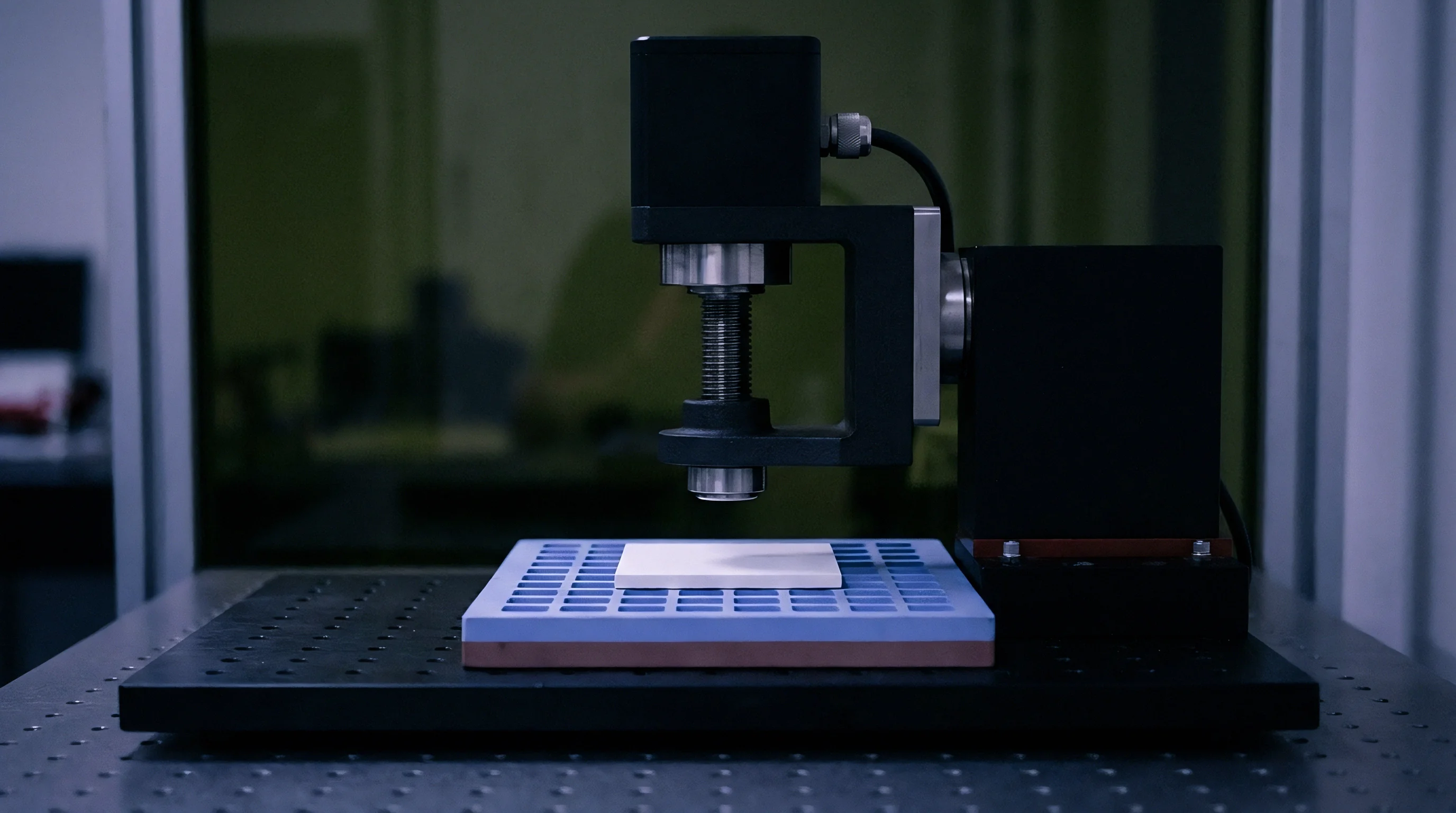

Phase
Temporal alignment between orthogonal vibration components governs the polarity and magnitude of the rectified direct-current offset. When an acceleration field applies sinusoidal forces along two orthogonal coordinates, displacement responses depend strictly on mechanical suspension transfer functions and relative drive angles. Let the mechanical input along the primary sense coordinate take the form of an alternating acceleration, while an orthogonal input acts simultaneously with a relative angle difference.
The resulting multi-dimensional motion induces nonlinear electrostatic and squeeze-film interactions within the capacitive microstructure.
Interelectrode capacitance across micromachined differential combs follows an inverse relationship with plate separation distance. Primary displacement changes the nominal finger gap symmetrically under ideal linear conditions. Concurrent orthogonal motion shifts the lateral overlap engagement between interlaced fingers.
The electrostatic sensing capacitance becomes the mathematical product of the engagement area and the inverse of the finger separation gap. Phase shifts alter everything.
Differential comb structures maintain bias stability only when orthogonal mechanical deflections preserve absolute mirror symmetry throughout the full dynamic displacement envelope.
Multiplication of two sinusoidal functions oscillating at identical frequencies yields a double-frequency harmonic combined with a frequency-independent direct-current term. The magnitude of this direct-current term depends strictly on the cosine of the relative mechanical phase angle between the two displacement vectors. At zero degrees phase difference, the rectification error reaches maximum positive amplitude.
At ninety degrees phase difference, the time-averaged product integrates toward zero, whereas a one-hundred-and-eighty-degree relationship drives the bias shift to maximum negative amplitude.
Squeeze-film gas damping between micromachined silicon plates introduces an additional phase-dependent force vector. When a proof mass moves rapidly within a sealed, low-pressure cavity, the trapped gas creates an air spring effect characterized by the dimensionless squeeze number. Lateral cross-displacement modulates the boundary leakage paths of the squeeze film, causing viscous damping forces to vary asymmetrically over the oscillatory cycle.
Damping asymmetry breaks balance.

Comb Overlap Modulation under Biaxial Motion
Differential capacitive readouts depend on balanced electrode geometries across moving finger arrays. The sensing plate arrangement relies on identical baseline gaps to eliminate common-mode electrostatic perturbations through differential charge integration.
- Electrostatic area modulation changes the active capacitive plate overlap proportionally to instantaneous cross-axis travel, multiplying the primary displacement signal by the orthogonal motion vector.
- Variable gap non-linearity produces higher-order inverse power terms during large primary-axis deflections, preventing complete cancellation of common-mode electrostatic forces.
- Squeeze-film boundary distortion alters gas escape velocity along the comb finger perimeter, generating an asymmetric damping reaction across opposing capacitor sets.
- Parasitic substrate capacitance couples ground plane potentials into floating proof mass structures, introducing voltage-dependent electrostatic spring softening during diagonal travel.

Transduction Bias Shifts across Phase Angles
Evaluation of diverse micro-electromechanical sensing architectures under dual-axis excitation demonstrates the decisive role of mechanical phase relationships. The table below outlines experimental measurements taken under orthogonal 1.2 kHz vibration fields with 10 g peak acceleration applied simultaneously across primary and cross axes under varying relative phase conditions.
| Transduction Principle | Comb Geometry | VRE at 0 deg Phase (mg) | VRE at 45 deg Phase (mg) | VRE at 90 deg Phase (mg) | VRE at 180 deg Phase (mg) |
|---|---|---|---|---|---|
| In-Plane Differential Capacitive | Standard Overlap Comb | +48.6 | +34.2 | +2.1 | -47.9 |
| In-Plane Differential Capacitive | Symmetric Gap-Closing | +62.1 | +43.8 | +3.4 | -61.5 |
| Out-of-Plane Differential Capacitive | Torsional Teeter-Totter | +84.3 | +59.5 | +5.8 | -83.7 |
| Piezoresistive Nano-Gauge | Direct Stress Beam | +11.2 | +7.9 | +0.9 | -11.0 |
| Resonant Beam Differential | Double-Ended Tuning Fork | +4.3 | +3.1 | +0.4 | -4.2 |
Component vendors frequently assert that symmetric differential layouts cancel out all secondary even-order cross-axis rectification artifacts by mathematical definition.


Tether
Mechanical suspensions engineered from single-crystal silicon exhibit linear elasticity across micro-scale deflections, yet large dynamic amplitudes engage geometric spring hardening. Micro-machined folded flexures or clamped-guided beam arrangements undergo non-linear axial tension when lateral deflections exceed five percent of beam thickness. Tension hardens silicon beams.
The restoring force departs from Hooke’s law, requiring third-order Duffing terms to describe dynamic mass restoring forces.
Consider an integrated tri-axial proof mass suspended by four symmetrical serpentine flexure springs. Deflection along the primary horizontal axis extends the spring beams, increasing the tension throughout the flexure web. This induced tension increases the effective mechanical spring constant governing orthogonal motion.
Orthogonal forces couple mechanically.
Silicon flexures subjected to multi-axis dynamic loads exhibit parametric stiffness modulation that cannot be modeled by decoupled single-degree-of-freedom equations.
When high-frequency vibration displaces the suspension along the primary coordinate at frequency omega, the orthogonal stiffness oscillates at twice that frequency. Should dynamic vibration also enter along the orthogonal axis at frequency omega, a parametric excitation condition occurs. The phase angle between the stiffness variation and the orthogonal displacement determines whether energy feeds into or dissipates from the orthogonal vibration mode.
The resulting mechanical limit cycle generates an asymmetric proof-mass orbit whose mean position departs from zero.

Can Cross-Axis Dynamic Coupling Exceed Linear Limits?
Linear vibration models assume that the mechanical transfer function along one axis remains independent of excitation along all other spatial directions. Under real operational environments, structural non-linearities invalidate this assumption at moderate dynamic loads. The physical coupling mechanisms responsible for driving suspension dynamics beyond linear response thresholds comprise specific structural behaviors:
- Stress stiffening in thin beams increases orthogonal resonant frequencies during large planar deflections, producing phase-dependent amplitude shifts in cross-axis displacement.
- Asymmetric mechanical travel limits cause abrupt contact stiffness jumps when excessive lateral motion brings the suspension into contact with anti-stiction stop bumpers.
- Torsional mode tilting converts planar shear stresses into out-of-plane rotational deflections, coupling z-axis comb fingers into substrate electrostatic fields.

Worked Bias Shift under Quadrature Vibration
To quantify the phase-dependent vibration rectification error, analyze a worked scenario based on published physical parameters for an industrial multi-axis capacitive inertial sensor. Assume a proof mass of 0.25 micrograms suspended by folded flexure beams with a nominal primary resonance frequency of 5.5 kHz and an orthogonal resonance frequency of 6.2 kHz. Let the nominal comb finger gap equal 1.5 micrometers, with an initial overlap length of 25 micrometers across 120 differential finger pairs.
Apply a simultaneous biaxial sinusoidal acceleration field at an excitation frequency of 2.0 kHz, with an amplitude of 12 g along the primary axis and 12 g along the orthogonal axis. The dynamic acceleration equations appear as follows:
a_x(t) = A_x sin(omega t)
a_y(t) = A_y sin(omega t + phi)
Here, A_x equals 117.72 meters per second squared, A_y equals 117.72 meters per second squared, omega equals 2 pi 2000 radians per second, and phi represents the spatial phase angle between the two vibration vectors. The primary mechanical displacement x(t) and orthogonal displacement y(t) follow steady-state dynamic response equations governed by the mechanical quality factor Q, assumed to equal 15 for both axes under sealed cavity pressure:
x(t) = X_0 sin(omega t – theta_x)
y(t) = Y_0 sin(omega t + phi – theta_y)
At 2.0 kHz, well below mechanical resonance, displacement amplitudes evaluate to X_0 = 101.4 nanometers and Y_0 = 79.8 nanometers. The phase lags relative to input drive equal theta_x = 0.141 radians (8.1 degrees) and theta_y = 0.109 radians (6.2 degrees). The differential sensing capacitance C_diff(t) is defined by the instantaneous overlap area and the inverse finger gap:
C_diff(t) = epsilon_0 N
Expanding this expression using a Taylor series approximation through second-order perturbation terms yields:
C_diff(t) = (2 epsilon_0 N / d_0)
The term of operational consequence is the cross-product x(t) y(t). Integrating this cross-product over one complete vibration period T = 2 pi / omega isolates the steady-state rectified DC capacitance shift Delta C_dc:
Delta C_dc = (2 epsilon_0 N / d_0^2) (1 / T) integral from 0 to T of dt
Delta C_dc = (epsilon_0 N / d_0^2) X_0 Y_0 cos(phi – theta_y + theta_x)
Substituting the physical constants: vacuum permittivity epsilon_0 = 8.854e-12 Farads per meter, finger count N = 120, baseline gap d_0 = 1.5e-6 meters, overlap length L_0 = 25e-6 meters, X_0 = 101.4e-9 meters, and Y_0 = 79.8e-9 meters. The sensitivity scale factor for linear primary motion equals 3.54 femtofarads per g. The effective phase lag offset (theta_x – theta_y) equals 0.032 radians (1.8 degrees).
Evaluating this rectification at a relative mechanical phase angle phi = 0 degrees produces a capacitance shift Delta C_dc = +0.0381 femtofarads. Dividing this value by the linear scale factor reveals an apparent acceleration bias shift of +10.76 milli-g. When the excitation phase shifts to phi = 90 degrees, the cosine argument evaluates near zero, yielding a DC bias shift of -0.34 milli-g.
Setting the vibration phase angle to phi = 180 degrees reverses the polarity, producing a DC bias shift of -10.76 milli-g. The bias shift remains permanent. When cross-axis vibration arrives in phase with primary excitation, geometric comb intermodulation generates false DC acceleration offsets directly proportional to the cosine of their relative phase.


Filter
Analog front-end circuitry downstream of the micromechanical die converts capacitive perturbations into discrete numerical representations. Switched-capacitor charge amplifiers, continuous-time transimpedance stages, synchronous demodulators, and sigma-delta analog-to-digital converters form the conversion signal path. Phase delays introduced by analog filters or synchronous demodulation clock skew convert high-frequency out-of-phase sensor signals into false direct-current outputs.
A continuous-time capacitive front end applies high-frequency carrier voltages to the proof mass, demodulating the resulting charge through phase-sensitive synchronous detectors. Demodulation clocks drift over temperature. If the local oscillator clock lags the mechanical vibration signal by an uncalibrated phase angle, cross-axis capacitive currents that normally cancel during orthogonal demodulation project directly onto the in-phase baseband axis.

Front-End Group Delay Mismatch across Channels
Tri-axial integrated circuits process three spatial channels through parallel signal paths. Manufacturing variations across on-chip resistors and capacitors produce channel-to-channel variations in analog anti-aliasing filter cutoff frequencies. A five-percent resistance tolerance across an active low-pass filter stage creates a group delay divergence between the x-axis and y-axis conditioning chains.
When high-frequency biaxial vibration stimulates the device, this group delay mismatch alters the apparent phase relationship between channels before analog-to-digital conversion. Even if an external vibration field maintains a quadrature phase angle that naturally suppresses mechanical rectification, the electronic filter network shifts the signal phase away from ninety degrees. The electronic phase error reintroduces second-order intermodulation, generating digital DC offsets inside the processing pipeline.

Will Continuous Force Feedback Eliminate Rectification Shifts?
Closed-loop micro-electromechanical sensors apply electrostatic forces to maintain the proof mass at its neutral null position, countering incoming mechanical acceleration. Electronic feedback holds the proof mass stationary, attenuating mechanical non-linearities arising from large flexure deflections.
Closed-loop architectures eliminate rectification only within the active tracking bandwidth of the feedback control loop. Micro-machined closed-loop control systems typically operate with loop bandwidths between 1.0 kHz and 3.0 kHz to maintain stability margins against high-Q mechanical resonance peaks. Vibration frequencies exceeding the feedback loop bandwidth bypass electrostatic rebalancing forces.
High-frequency forces move the proof mass freely, re-establishing geometric non-linearities and drive-phase-dependent rectification errors.
| Signal Conditioning Architecture | Loop Bandwidth (kHz) | Sampling Rate (kSps) | Channel Phase Tracking (deg) | Peak Rectification (mg/g^2) |
|---|---|---|---|---|
| Open-Loop Switched-Capacitor | N/A (Open) | 200 | ± 4.8 | 1.85 |
| Open-Loop Continuous-Time AM | N/A (Open) | 500 | ± 1.2 | 0.72 |
| Closed-Loop Analog Force-Feedback | 1.5 | 100 | ± 3.1 | 1.14 |
| Closed-Loop Sigma-Delta Rebalance | 2.8 | 1200 | ± 0.4 | 0.21 |
| Digital Closed-Loop Resonant Drive | 0.8 | 48 | ± 6.5 | 3.40 |
Front-end calibration sequences verify dynamic phase balance through automated factory alignment procedures:
- Inject synchronous dual-channel electrostatic excitation signals via dedicated self-test electrodes to bypass mechanical package dynamics.
- Sweep the excitation phase angle across 360 degrees in discrete 5-degree increments while recording baseband DC offset registers.
- Compute the fundamental Fourier component of the resulting DC offset curve to isolate the electronic phase skew parameter.
- Adjust on-chip programmable capacitor trims within the demodulation clock generator to align baseband phase nulls with quadrature excitation points.
- Execute full-amplitude dynamic checks to confirm that front-end transimpedance stages remain within their linear voltage swing range.
Modulator saturation forces output clipping. When intense out-of-band vibration overloads the analog-to-digital converter input stage, the asymmetric clipping of sinusoidal peaks produces catastrophic DC bias shifts exceeding several hundred milli-g. Calibration cannot fix structural clipping.
Inertial navigation systems operating through unmitigated sensor saturation integrate these false DC biases into runaway velocity calculation errors that degrade positional accuracy within seconds.


Acceptance
Component procurement specifications routinely define vibration sensitivity using single-axis vibration rectification coefficients expressed in micro-g per g squared. Sourcing engineers accept components based on datasheets quoting single-axis test conditions executed according to simplified protocols. Dual-axis shakers remain scarce.
Multi-axis vibration environments encountered in automotive powertrain control, guided munitions, and downhole directional drilling introduce phase-coupled dynamic loads that single-axis qualification sweeps fail to reveal.
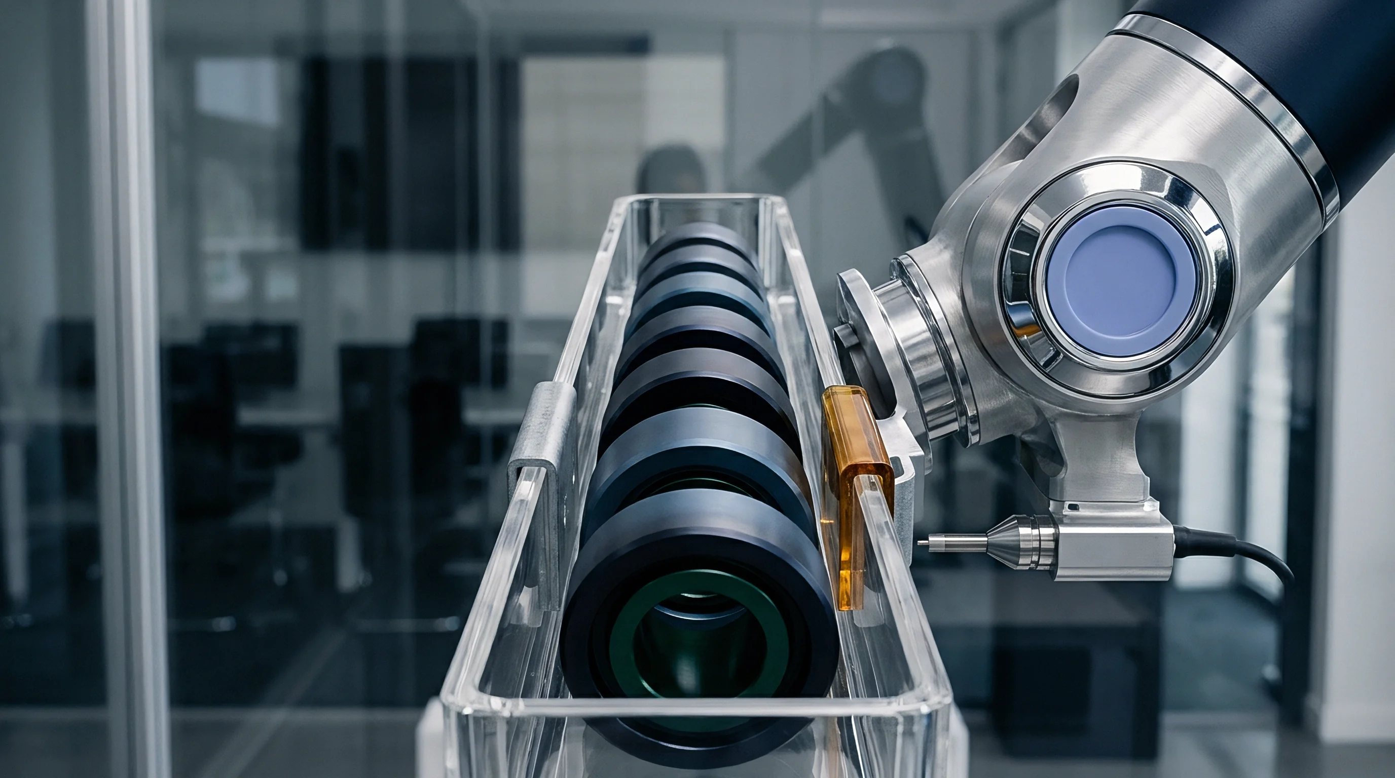
Incoming inspection procedures must incorporate simultaneous multi-axis dynamic vibration screens to detect phase-dependent rectification vulnerabilities. Dual-axis electrodynamic shakers drive test fixtures along two orthogonal axes using independent power amplifiers driven by synchronized arbitrary waveform generators. Testing components across phase angles from zero to one hundred and eighty degrees exposes parts with latent structural asymmetry or packaging stress imbalances.
Standard qualification schedules omitting dual-axis phase-swept vibration testing allow components with excessive intermodulation rectification to pass directly into mission-critical hardware production.

Dual-Axis Shaker Screening Protocols
Verification protocols based on international standards govern mechanical shock and vibration qualification for electronic instrumentation. ISO 16063-16 specifies methods for testing vibration sensitivity in inertial sensors, yet the standard focuses primarily on single-axis linear sweeps. Evaluating multi-axis phase rectification requires augmenting conventional test matrices with synchronized cross-axis multi-sine excitation profiles.
The test system applies a continuous 10 g root-mean-square acceleration profile across two orthogonal coordinates while continuously stepping the relative drive phase angle through four quadrants. Data acquisition systems record the low-pass filtered zero-g bias offset at each phase increment, tracking bias migration relative to baseline quiescent values. Parts displaying peak-to-peak bias variance exceeding specified design thresholds are flagged for package stress anomalies or comb finger mask misalignments.
Supplier Screening Realities and Landed Costs
Automotive and industrial qualification standards, including AEC-Q100 and AEC-Q103-002, mandate rigorous environmental testing but stop short of requiring phase-swept biaxial dynamic screening during high-volume production wafer sort or package test. Production testing relies on rapid single-axis electrostatic self-test checks to minimize handler index times. Static calibration misses dynamic rectifications.
Yield drops ten percent. Demanding multi-axis phase rectification verification during incoming batch acceptance increases component costs due to supplier test overhead and package rejection rates. The table below delineates procurement costs, qualification levels, and rectification tolerances across typical multi-axis MEMS accelerometer sourcing categories.
| Quality Grade | Qualification Standard | Dynamic Rectification Test Method | Phase-Swept VRE Limit (mg/g^2) | Landed Unit Cost (USD) |
|---|---|---|---|---|
| Commercial Consumer | JEDEC JESD22 | Single-Axis Static Tumble Only | Not Specified | $0.45 – $1.20 |
| Industrial Standard | IEC 60068-2-6 | Single-Axis Sine Sweep (100 Hz – 2 kHz) | $3.50 – $8.00 | |
| Automotive Grade 1 | AEC-Q100 Grade 1 | Single-Axis Random (20 Hz – 2 kHz) | $6.80 – $14.50 | |
| High-Rel Industrial | AEC-Q103-002 | Dual-Axis Quadrature Sine Sweep | $22.00 – $48.00 | |
| Tactical Defense | MIL-STD-810H | Tri-Axis Orbital Phase-Swept Matrix | $180.00 – $450.00 | |
| Test methodology data derived from incoming lot inspection screening reports; pricing reflects 10,000-unit procurement volumes. | ||||
Procurement agreements governing safety-critical inertial units incorporate explicit specification clauses defining maximum allowable DC output migration under simultaneous dual-axis dynamic loading. Purchase contracts referencing AEC-Q103-002 require suppliers to warrant that the differential vibration rectification error across all orthogonal phase combinations remains below 0.5 milli-g per g squared from 500 Hz to 5 kHz. This contractual clause obligates the silicon foundry to reject packaging lots showing excessive die-attach warpage, shifting the financial burden of mechanical rectification scrap entirely to the vendor.