Isolating Sensor Array Zero Shift from Fixture Expansion
Isolating sensor array zero shift requires CTE-matched flexure carriers and differential thermal matrix calibration to eliminate fixture strain.

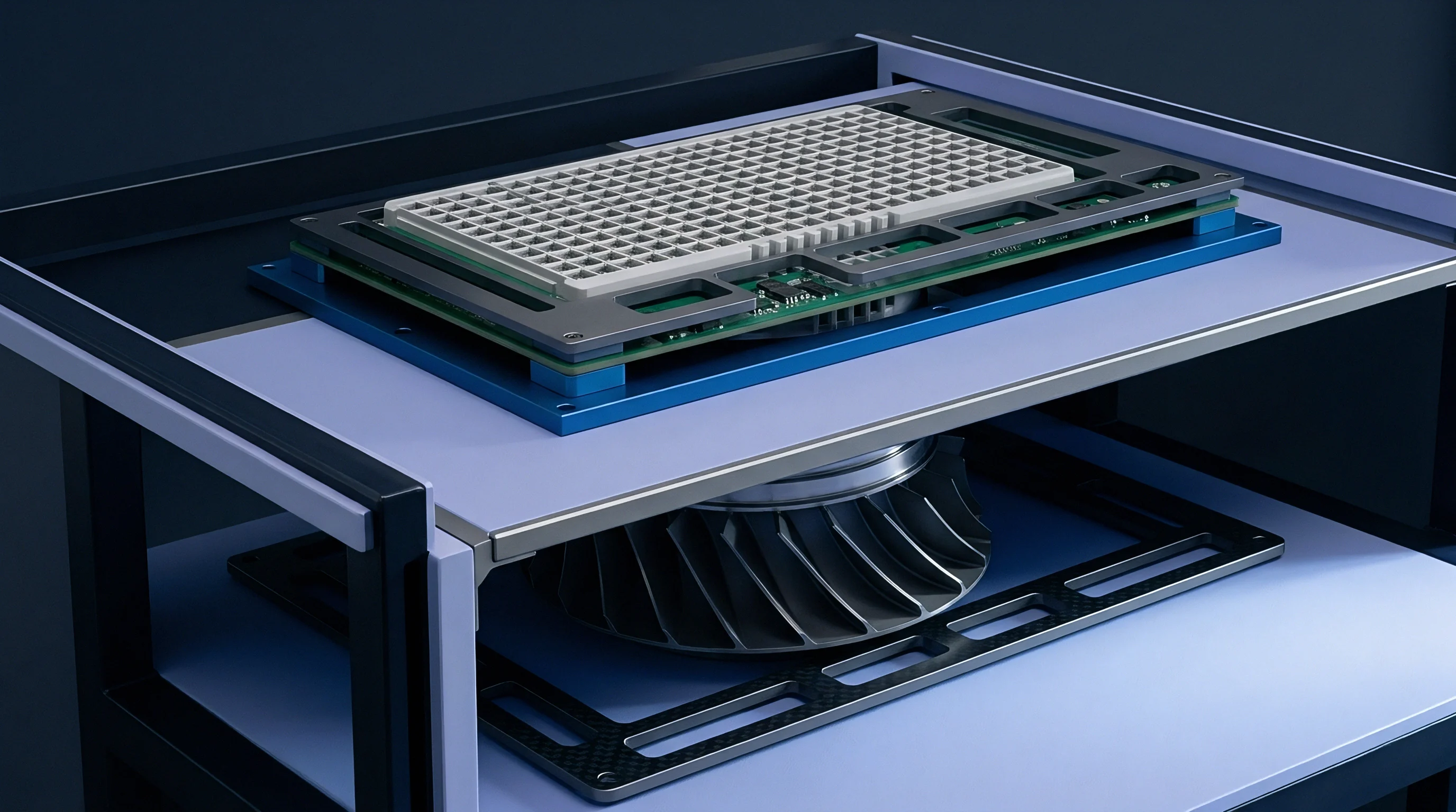
Deformation
Thermal gradients across high-density sensor arrays generate mechanical stress before any external load contacts the transducer face. When ambient or operational temperatures shift, the mounting block expands at a rate determined by its coefficient of thermal expansion, while the sensor substrate expands according to its own material lattice properties. This mismatch forces strain across the mechanical interface, bending the active sensing elements and producing an electrical signal indistinguishable from an actual measurand input.
Consider a multi-element piezoresistive strain or pressure array bonded directly to an aluminum mounting housing. Aluminum 6061-T6 exhibits a coefficient of thermal expansion of approximately 23.0 parts per million per kelvin, whereas monocrystalline silicon substrate moves at roughly 2.6 parts per million per kelvin. A thermal shift of 20 kelvin creates a differential free expansion strain of over 400 microstrain at the interface joint.
If the mounting fasteners or adhesive bonds transfer even half of this strain to the active bridge channels, the resulting zero shift consumes a major portion of the total sensor error budget.
Expansion simulates force. Heat shifts the baseline. Mechanical strain transfer efficiency across the housing-to-sensor boundary depends on assembly geometry, joint compliance, and material elasticity.
When a rigid fixture restricts substrate growth, the trapped energy forces localized micro-bowing across the array surface. This bowing creates structural displacement across differential sensing elements, causing baseline output to wander even under zero external load.
| Fixture Material | Substrate Material | Fixture CTE (ppm/K) | Substrate CTE (ppm/K) | Differential CTE (ppm/K) | Induced Strain at 25 K Delta (microstrain) |
|---|---|---|---|---|---|
| 6061-T6 Aluminum | Monocrystalline Silicon | 23.0 | 2.6 | 20.4 | 510 |
| 304 Stainless Steel | Monocrystalline Silicon | 17.3 | 2.6 | 14.7 | 367.5 |
| AISI 4140 Alloy Steel | Alumina Ceramic (96%) | 12.2 | 7.2 | 5.0 | 125 |
| Invar 36 Alloy | Monocrystalline Silicon | 1.2 | 2.6 | -1.4 | -35 |
| Titanium Grade 5 | Alumina Ceramic (96%) | 8.6 | 7.2 | 1.4 | 35 |
Quantifying thermal strain transfer requires modeling both the shear modulus of the interposer layer and the aspect ratio of the contact footprint. Thicker adhesive layers with low shear moduli absorb differential growth, reducing mechanical strain transmission to the active element. However, viscoelastic material properties introduce hysteresis during rapid thermal cycling.
The housing expands during heating, dragging the bond line outward, but structural relaxation delays return to the baseline upon cooling. The sensor array retains residual stress, manifesting as baseline offset drift that fails to clear until long after thermal equilibrium is re-established.
Thermal expansion of a 6061-T6 aluminum mounting fixture introduces 23.0 microstrain per kelvin of apparent zero shift in an unconstrained silicon sensor array.
Fastener pre-load alters this strain transfer dynamic significantly. Torque applied to fixture bolts creates localized stress fields that expand non-uniformly when heated. Clamping zones experience higher compressive forces, generating spatial gradients across the sensor array plane.
As a result, outer sensing elements in a linear or matrix array register higher thermal zero shifts than center elements, skewing spatial calibration matrices.
Misattributing mechanical fixture expansion to internal sensor element drift leads engineering teams to reject perfectly stable sensor lots while leaving defective mounting geometries in active production.

Decoupling
Physical isolation techniques intercept thermal strain before expansion energy crosses into the sensor array housing. Rather than attempting to compensate for structural displacement mathematically after signal digitization, mechanical flexures and strain-isolating sub-carriers absorb differential dimensional changes at the structural boundary. Controlling compliance along specific axes allows the assembly to maintain rigid measurement vector support while remaining soft against thermal growth directions.
Kinematic mounts provide designated degrees of freedom that decouple fixture growth from the transducer base. Ball-in-groove interfaces, flexure blades, and dual-pin sliding joints allow the fixture body to swell freely without transferring bending moments to the array chassis. Flexure elements machined directly into an intermediate sub-carrier reduce thermal strain transmission by several orders of magnitude compared to direct bolted flanges.
Invar stops the strain. Joints slip at temperature. Mounting high-precision arrays to an intermediate carrier fabricated from low-expansion alloys creates a stable thermal buffer.
The intermediate carrier matches the expansion behavior of the sensor substrate, while flexible mounting legs interface with the high-expansion machine base. The high-expansion fixture flexes the carrier legs without deforming the central mounting pad where the active array sits.
- Kinematic Flexure Legs permit radial thermal growth of the main machine frame while preserving precise sub-micron central axis positioning for the array.
- Invar Sub-Carriers act as an intermediate thermal expansion buffer between high-expansion aluminum housings and low-expansion ceramic or silicon substrates.
- Symmetrical Mounting Geometries distribute thermal strain evenly across array elements, preventing differential twisting and asymmetric offset shifts across channels.
- Low-Friction PTFE Interposers reduce shear stress transmission across planar contact surfaces during slow thermal stepping cycles.
Design selection depends heavily on target bandwidth and environmental vibration requirements. High compliance in flexure mounts protects sensor channels from thermal zero wander, but low mounting stiffness lowers the mechanical resonant frequency of the sensor package. If the assembly resonant frequency dips into the operational frequency band of the application, dynamic vibration amplifies structural noise, destroying signal-to-noise ratio performance.
Gasket materials and bond line thickness demand precise dimensioning. Silicone adhesives provide excellent strain relief due to low shear modulus, but high gas permeability exposes internal circuitry to moisture ingress, driving secondary drift mechanisms. Epoxies offer robust environmental protection and high structural stiffness, yet high elastic moduli transmit thermal strain directly into the array structure.
Flexure stiffness parallel to the primary measurement axis ought to exceed cross-axis isolation compliance by at least two orders of magnitude to keep mechanical strain crosstalk below the instrumentation noise floor.

Separation
Distinguishing internal transducer offset drift from external mechanical fixture strain relies on signal decomposition and matrix calibration techniques. Sensor elements respond to net strain, regardless of whether stress originates from measured physical quantities, internal substrate aging, or housing thermal expansion. Isolating the specific contribution of fixture expansion requires auxiliary reference elements and multi-variable mathematical models built during factory characterization.
Differential bridge topologies separate pure temperature responses from mechanical strain vectors. Placing unconstrained dummy sensing elements within the sensor package exposes those reference channels to ambient thermal changes without subjecting them to fixture-induced mechanical strain. Subtracting the dummy channel output from active array outputs isolates the mechanical strain component imposed by fixture expansion.
The math breaks down. Data hides fixture motion. When physical dummy elements cannot fit into compact array geometries, spatial temperature mapping combined with multi-term polynomial compensation matrices extracts offset errors.
High-density arrays incorporate embedded RTDs or diode temperature sensors placed adjacent to active sensing zones. The measurement system feeds local temperature measurements into a calibration matrix derived during multi-point thermal stepping routines under zero-load conditions.
| Separation Technique | Computational Complexity | Hardware Overhead | Residual Offset Uncertainty | Thermal Response Bandwidth |
|---|---|---|---|---|
| Differential Dummy Element Subtraction | Low | Medium (Requires extra bridge channels) | 0.02% Full Scale | High (Real-time tracking) |
| Polynomial Matrix Temperature Compensation | High | Low (Uses embedded thermistors) | 0.08% Full Scale | Medium (Thermal lag sensitive) |
| Dual-Wavelength Optical Baseline Subtraction | Very High | High (Requires optical reference source) | 0.005% Full Scale | Very High (Sub-millisecond) |
| Invar Reference Strain Gauge Channel | Medium | Medium (Requires external strain monitoring) | 0.03% Full Scale | High (Direct strain measurement) |
A multi-variable zero calibration equation accounts for thermal lag between the outer fixture housing and internal array elements. Rapid thermal transients generate steep thermal gradients across the mounting interface. During transient conditions, internal thermistors register a lower temperature than the expanding outer housing, leading simple static temperature compensation algorithms to miscalculate mechanical strain forces.
Dynamic compensation models incorporate time derivatives of temperature to adjust correction factors during thermal ramps. Including first-order and second-order thermal rate terms prevents the calibration matrix from over-correcting during heating cycles and under-correcting during cooling cycles. This prevents artificial hysteresis loops from corrupting real-time array zero readings.
Specifications following ISO 21745 require zero-stability figures to document the mechanical constraint state of the housing during thermal calibration cycles.
Array manufacturers frequently claim zero drift values published on datasheets reflect isolated sensor performance, leaving fixture thermal strain compliance to the system integrator.

Verification
Bench testing protocols must isolate thermal expansion strain from true sensor element degradation through controlled environmental stepping and optical reference tracking. Validating sensor stability requires uncoupling the array from mechanical constraints while cycling temperature across the full specified operating range. Testing arrays in both constrained production fixtures and unconstrained free-floating conditions surfaces the precise strain transfer magnitude of the assembly.
Metal creeps under stress. Bolts lose tension. Chamber time adds cost.
Laser doppler vibrometry or dual-channel optical interferometry measures microscopic dimensional expansion of the fixture during thermal steps. Comparing measured physical movement of the fixture frame directly against the sensor array output voltage yields an exact empirical strain transfer ratio.
Why Do Thermal Stepping Tests Miss Fixture Hysteresis?
Standard environmental tests often advance thermal steps too quickly, logging data before structural relaxation completes. Fixture joint interfaces and mounting bolts experience mechanical creep under sustained thermal stress. Fast temperature ramps mask this creep, presenting apparent stability during test transitions while hiding long-term zero drift that appears only after hours of dwell time at elevated temperatures.
A thermal isolation flexure pays for its machining cost by halving the required calibration chamber dwell time during array zero trimming.
Execution of a rigorous isolation bench test follows a structured sequence to separate environmental noise from structural expansion shifts.
- Mount the sensor array in an unconstrained, free-floating baseline carrier inside the thermal chamber without applying torque to external mounting tabs.
- Cycle thermal chamber temperature across the specified operating band in 10-kelvin increments, holding each temperature step for 60 minutes to establish thermal equilibrium.
- Record raw zero-output baselines for all array channels across the unconstrained thermal cycle to establish true internal sensor zero shift coefficients.
- Install the sensor array into the production fixture, applying specified fastener torque using a calibrated micro-torque wrench.
- Repeat the multi-step thermal cycle, recording channel zero outputs at identical temperature stabilization points.
- Subtract unconstrained baseline channel outputs from constrained fixture test data to yield the net zero shift vector driven solely by fixture expansion.
Discrepancies between heating and cooling curves during constrained testing indicate mechanical hysteresis within the fixture assembly. Slippage along bolted joint faces or micro-yield events in low-grade mounting metals show up as permanent baseline offsets after returning to 23 degrees Celsius. If zero offset remains after complete thermal stabilization at ambient conditions, joint relaxation or fastener yield has altered the assembly pre-load state permanently.
How much residual zero uncertainty can high-reliability systems accept when long-term bolt torque relaxation continuously alters the strain transfer coefficient over five years of field operation?
Economics
Achieving absolute zero-point stability across wide thermal ranges introduces direct cost escalations in housing materials, machining tolerances, and calibration chamber residence times. Specifying overly tight zero-shift limits without addressing fixture expansion drives unnecessary scrap rates during end-of-line verification tests. Aligning tolerance requirements with true system-level accuracy needs prevents over-specifying hardware components.
Selecting low-expansion alloys like Invar 36 increases raw material procurement expenses by a factor of eight compared to standard 6061 aluminum stock. Machining costs increase further because nickel-iron alloys exhibit high work-hardening rates, accelerating tool wear and extending cycle times on modern CNC milling centers. Titanium components lower weight while offering intermediate thermal expansion matching, but require specialized cutting fluids and rigid machine setups.
Yield drops fast. Precision carries high cost. Thermal gradient creates offset.
Calibration chamber residence time represents a significant driver of manufacturing overhead. Extending soak times from 15 minutes to 60 minutes per temperature step ensures structural equilibrium, but cuts total daily calibration bench throughput by 75 percent, forcing capital investment in additional environmental test chambers.
- Housing Material Grade dictates baseline mechanical strain transfer; upgrading from aluminum to Invar increases raw material cost while eliminating 90 percent of fixture expansion strain.
- Calibration Dwell Time directly multiplies per-unit test expenses; longer soak times yield higher accuracy data but constrain production volume.
- Kinematic Mount Machining Tolerances demand tight dimensional control, adding process steps such as wire EDM or high-precision grinding.
- Secondary Channel Calibration increases micro-controller pin counts and ADC sample time requirements, elevating overall electronics bill of materials costs.
Warranty exposure stemming from uncompensated zero shift surfaces long after field deployment. Sensor arrays specified for outdoor or industrial environments suffer field returns when seasonal temperature swings cause offset wander beyond application control limits. Quality teams misdiagnosing fixture joint creep as sensor array degradation waste failure analysis resources replacing functional sensor modules while leaving flawed fixture mounting designs in service.
Apparent sensor degradation in field returns routinely traces back to joint creep in low-cost fixture hardware rather than active element failure.
Including mandatory thermal zero-return limits under ISO 10012 Section 7.2 shifts thermal soak chamber costs to the sensor supplier and forces explicit documentation of fixture boundary constraints.