Electrical Interference
Voltage measurement errors within precision instrument circuits arise from small electromotive forces generated at the junctions of dissimilar metals when a temperature differential exists between points. This localized thermal emf governs the drift in low level analog signals where sub millivolt precision is required for accurate pressure or temperature sensing. It binds the choice of connector materials and wire types to the target noise floor of the amplifier board within the sensor housing.
This effect stops interfering at scales where the signal voltage is large enough to ignore minor millivolt offsets, typical in high power power distribution but critical in microelectronics. Quantifying this parasitic source identifies the limit where electrical measurement accuracy stops being about ADC resolution and starts being about the physical layout of the thermal thermal board.
Junction Potential
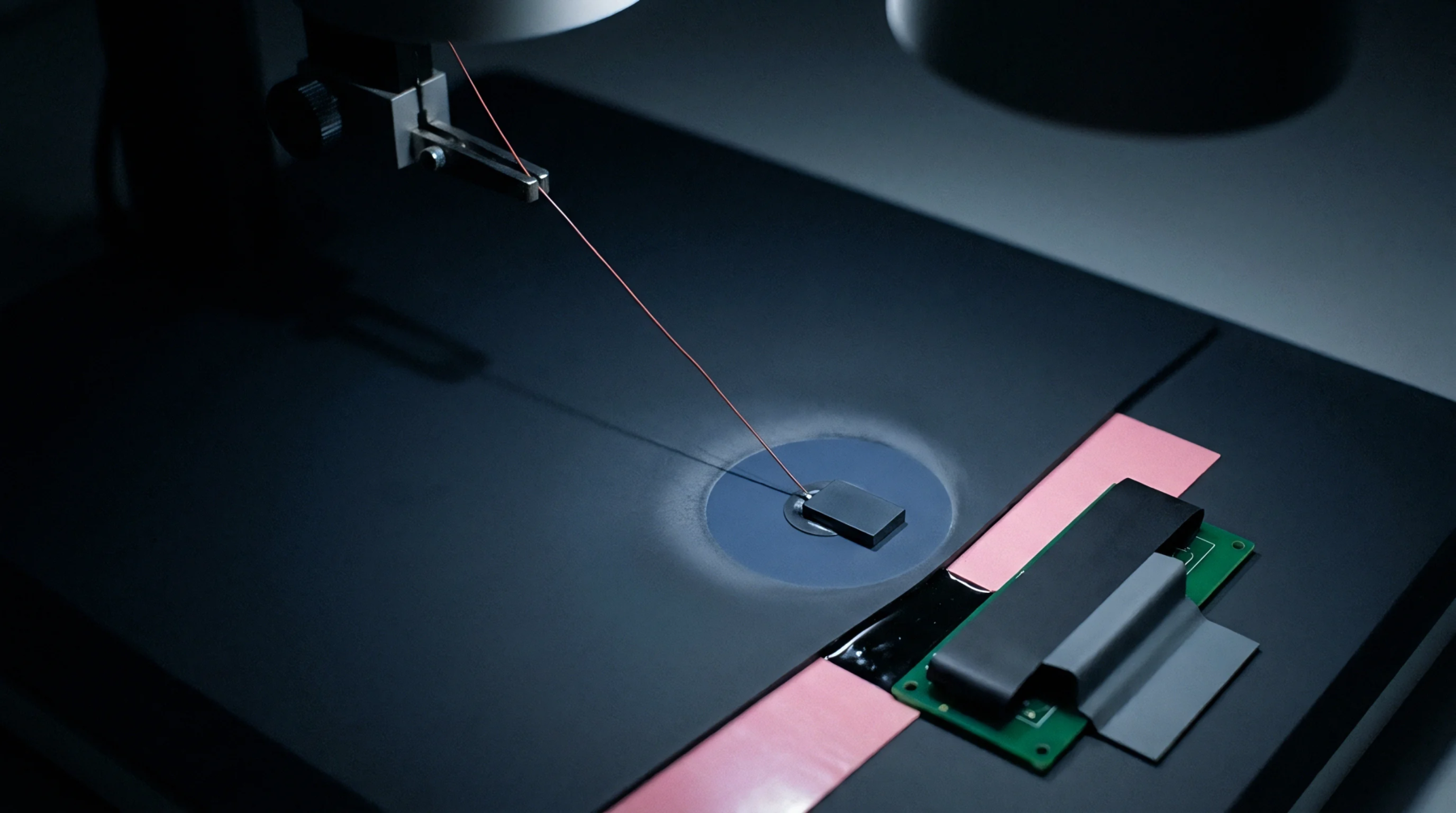
Heat shifts across a printed circuit board move atoms inside solder joints and copper traces to create a natural battery effect that mirrors the behavior of a thermocouple. These voltages from thermal emf appear whenever cooling fans create gradients or when high heat components sit near sensitive signal traces on the edge of the module. Systematic subtraction of these errors is difficult because they fluctuate in real time as the system warms up after being turned on.
Engineers utilize specific layout patterns, such as placing traces close together in isothermal zones, to encourage the cancellation of opposing voltages at identical junctions. Gold plating and the use of identical metals in connector pins minimize the primary generation of these signals at the interface points of critical measuring probes.
Signal Drift
Accuracy in nanovolt meters is eroded whenever technicians use incorrect cable materials or when ambient drafts move over exposed circuit pins during verification cycles. Performance loss through thermal emf erodes the low speed stability of high performance benchmarks used in secondary laboratories to calibrate reference standards. Metrology check sequences verify this error by shorting the input leads and measuring the non zero offset that remains as the test leads are handled by gloved fingers.
Tolerance levels for offset stability are typically set near five microvolts per degree Celsius, with premium instruments using specific drift compensation techniques inside the housing. Periodic checking of the thermal isolation shields ensures that heat remains uniform across the sensitive input stage where common mode rejection limits are identified.
Measurement Integrity
Consistent baseline results require the systematic elimination of thermal variances from the electrical test points before sensitivity counts are finalized. Detailed thermal emf assessments allow developers to choose better insulation packages that maintain uniform conditions inside the data logger across entire shift durations. High fidelity sensors attest to their reliability by showing minimal shift in output even when subjected to intense thermal shocks that would drive lesser hardware into error saturation.
Verification certificates note the ambient test conditions specifically to allow readers to factor in potential junction effects during their own secondary verification routines. Reliable circuit protection maintains the signal to noise ratio required for deep space or deep water instrumentation deployments where recalibration is not possible.