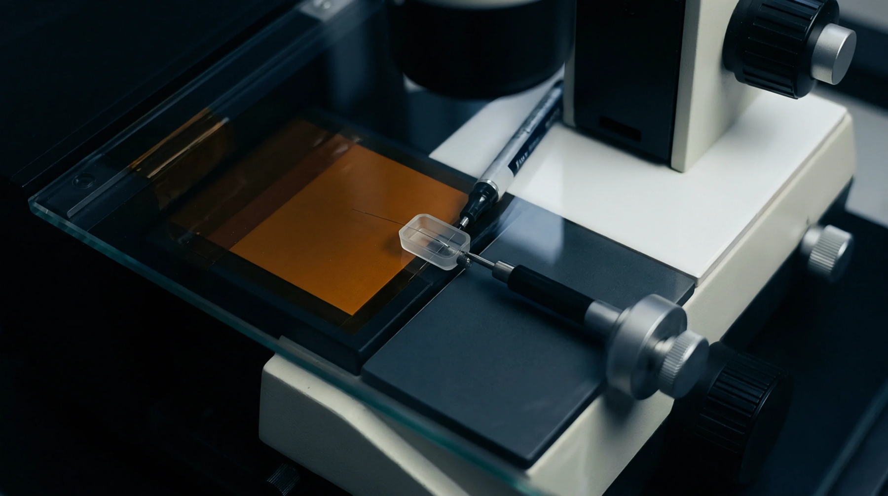
Sensor Adjustment
Absolute optical transducer calibration establishes the relationship between raw photodetector output voltages and true angular displacement under specified thermal and mechanical baselines. Optical encoder systems rely on fine grating scales and photoelectric sensors to translate rotary or linear motion into digital quadrature pulses. Signal processing electronics convert these analog photocurrent fluctuations into square wave outputs that drive subsequent motion controllers.
Environmental conditions alter the optical density of the disc substrate and thermal expansion shifts the relative position of the reading head. Metrological traceability requires comparing device output against a primary angular standard under controlled laboratory conditions to eliminate systematic interpolation errors.
Reference Drift
Temperature gradients across the scale carrier induce differential expansion that distorts the grating pitch and introduces periodic measurement errors into the position feedback loop. Diode aging decreases optical intensity at the photodetector array, which reduces the signal amplitude margin required for reliable quadrature decoding. Mechanical runout from mounting eccentricity generates a once-per-revolution sinusoid that superimposes onto the incremental position data.
Restoring specified performance demands measuring output deviation across the entire operating range and applying correction factors to the digital signal processing firmware.
Calibration Protocol
Factory verification procedures feed reference signals into the optical encoder while recording corresponding digital word outputs across multiple full rotations. Technicians evaluate peak-to-peak amplitude variations and phase offsets between sine and cosine channels to ensure proper interpolation accuracy. Calibration standards dictate that ambient temperature remains regulated during the test sequence to isolate thermal effects from intrinsic transducer linearity.
Output signals that exceed designated error bands trigger corrective gain adjustments within the internal conditioning circuitry until repeatability meets stated tolerances.
Post-Adjustment Verification
Field deployment exposes the measurement assembly to mechanical shock and vibration loads that can degrade the applied calibration offsets over operational lifespans. Periodic verification routines compare the transducer feedback against an independent secondary reference while the axis traverses a known fixed arc. Residual errors persisting after the adjustment phase indicate mechanical hysteresis within the coupling shaft or permanent degradation of the internal light emitting diode.
System reliability depends entirely on maintaining the integrity of these stored compensation tables throughout the mechanical lifecycle of the sensor.