Fixture Architecture
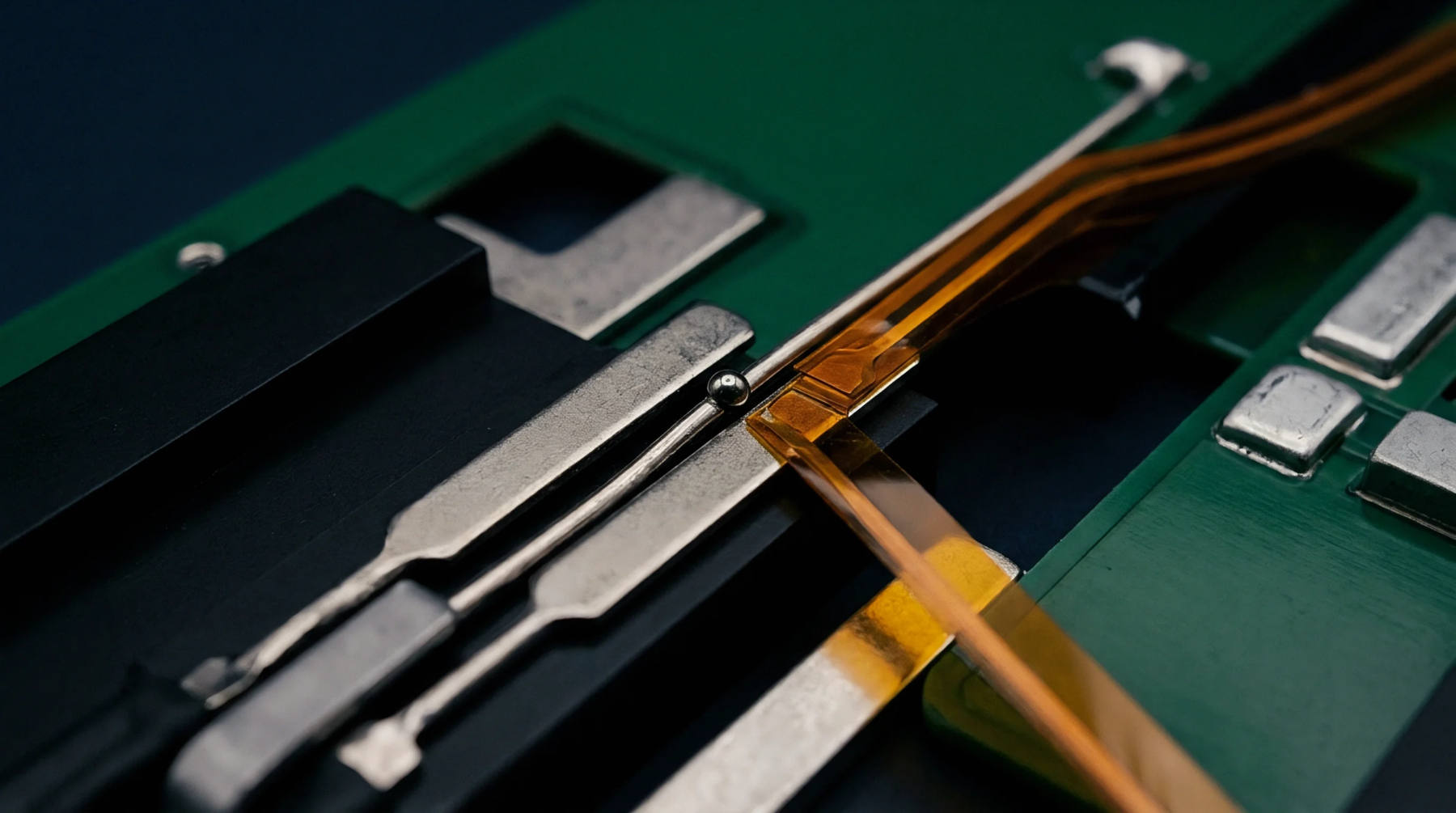
Automated test fixtures interface spring-loaded pogo pins directly with printed circuit board test pads to isolate individual components electrically. A bed-of-nails ICT rig holds a mechanical bed containing custom-machined receptacles fitted with spring probes, aligning each probe tip to a dedicated surface land on the unit under test. Mechanical actuation brings the populated assembly downward against spring force via pneumatic cylinders or vacuum draw, creating simultaneous electrical contact across all populated circuit nodes.
The test sequence evaluates passive component values, trace continuities, orientation of polarized devices, and solder bridges across adjacent conductors prior to full board powering. It stops applying once trace density or micro-vias remove physical clearance required for standard contact targets.
Guarding Circuitry
Operational amplifiers and active feedback paths neutralize parallel current flow during in-circuit passive component evaluations. During an analog interrogation on a bed-of-nails ICT platform, adjacent circuit branches that would otherwise shunt the component under test receive matched electrical potentials from operational buffer drivers, preventing diversionary currents from corrupting the reading. Four-wire Kelvin probe assignments run dual paths to individual test lands, bypassing probe contact resistance and internal fixture lead resistance during milliohm measurements.
Without active guarding, parallel networks distort observed resistances and inductances beyond allowable tolerance bands. The guarding technique reaches an absolute physical limit when operational amplifier output current limits are exceeded or when reactive parallel networks induce phase shifts that destabilize the guarding loop into oscillation.
Contact Resistance
Spring fatigue and flux accumulation on probe tips degrade measurement reproducibility over consecutive compression cycles. Mechanical wear dulls plunger facets, reducing contact force against test pads and increasing parasitic resistance from 50 milliohms to several ohms. False component rejections occur when this resistance exceeds allowable guard bands.
Probe life limits dictate scheduled pin replacement when spring forces degrade.
Verification Protocol
Calibration fixtures fitted with known reference standards qualify tester measurement paths before production runs commence. Systematic continuity sweeps map path resistance across the fixture interface, validating receiver pin connections against internal source-measure electronics. Gauge repeatability calculations quantify measurement uncertainty against factory quality thresholds over repeated fixture actuation cycles.
Traceability remains tied to annual laboratory calibrations of the internal digital multimeter and matrix switching cards. Acceptance criteria mandate that systemic measurement error from the bed-of-nails ICT hardware remains below ten percent of the tolerance band permitted for any inspected component.