Evaluating Board Footprint Tradeoffs in Discrete Sensor Implementation
Discrete sensor package choices determine board area, mechanical strain sensitivity, bus routing complexity, assembly yield, and final unit landed cost.


Geometry
Determining component real estate on a printed circuit board involves assessing physical package dimensions alongside manufacturing keep-out clearances. Silicon vendors present nominal package measurements in promotional literature, yet true layout footprints include solder mask expansions, placement machine tolerances, rework tool access envelopes, and trace breakout zones. A bare silicon die packaged in Wafer Level Chip Scale Packaging (WLCSP) presents the smallest physical area, but its land pattern demands microvia-in-pad technology and tight line-space rules that force additional board layers.
Moving to a Dual Flat No-Lead (DFN) or Land Grid Array (LGA) package increases mechanical body dimensions while simplifying assembly rules and trace routing.

Package Spatial Footprint and Land Pattern Realities
Direct surface-mount silicon solutions occupy variable physical boundaries depending on termination structure. WLCSP devices collapse the interconnect matrix directly onto the silicon footprint, using solder bumps at pitches down to 0.35 mm. While a 1.2 mm by 1.2 mm WLCSP occupies only 1.44 mm² of raw surface area, IPC-7351B guidelines mandate a surrounding keep-out perimeter of 0.5 mm to prevent solder bridging during reflow and to permit automated optical inspection.
DFN packages with a 2.0 mm by 2.0 mm plastic body require land patterns extending 0.25 mm beyond each edge for fillet formation, resulting in a functional footprint of 6.25 mm².
LGA options offer an intermediate spatial compromise, encapsulating sensitive microstructures within a molded cavity while presenting flat land pads on a 0.5 mm pitch. LGA footprints demand precise stencil aperture design to prevent bridging beneath the package center where structural ground pads sit. When component spacing drops below 0.3 mm pitch limits, standard PCB fabricators charge line-item premiums for laser-drilled microvias and advanced high-density interconnect (HDI) processing.
IPC-7351B nominal land pattern dimensions for a 2.0 mm by 2.0 mm LGA package require an extended pad length of 0.35 mm beyond the component termination to achieve a maximum failure rate below 12 dppm under thermal cycling.
Comparing discrete package options requires analyzing both primary component boundaries and peripheral clearance zones. The spatial footprint evaluation matrix establishes these trade-offs across standard package categories.
| Package Type | Body Size (mm) | Land Pattern Area (mm²) | Minimum Pitch (mm) | Keep-Out Margin (mm) | Required PCB Tech |
|---|---|---|---|---|---|
| WLCSP-6 | 1.20 x 0.80 | 1.96 | 0.35 | 0.50 | HDI Microvia Pad |
| DFN-8 | 2.00 x 2.00 | 6.25 | 0.50 | 0.30 | Standard Through-Hole Via |
| LGA-12 | 2.50 x 3.00 | 12.25 | 0.50 | 0.40 | Standard Dog-bone Via |
| SOIC-8 | 4.90 x 3.90 | 38.50 | 1.27 | 0.60 | Standard Conventional |
| Populated Module | 12.00 x 12.00 | 196.00 | 2.54 | 1.00 | Single-Layer Basic |
| Data compiled across IPC-7351B density level B standards for nominal surface mount assembly conditions. | |||||

Routing Density and Layer Count Consequences
Escalating interconnect pin counts beneath fine-pitch silicon forces layout designers to allocate dedicated escape channels. A 12-pin LGA package with a 0.5 mm pin pitch permits single-trace escape routing between adjacent pads using standard 0.10 mm trace width and spacing rules. Dropping pin pitch to 0.4 mm eliminates trace-between-pad routing on top copper layers, compelling designers to drop vias inside pads or add internal signal layers.
Trace routing channel calculations determine whether a four-layer PCB stack-up accommodates a sensor array or whether six layers become necessary. Adding two PCB layers across a 100 mm by 100 mm panel increases raw fabrication costs by approximately 35 percent to 45 percent at mid-volume quantities. Integrating discrete sensing elements into constrained edges requires accounting for mechanical routing channel allocations alongside copper clearance rules.
Selecting a minimal footprint without accommodating stencil clearance causes solder bridging across fine-pitch pads, forcing manual rework that destroys board substrates.

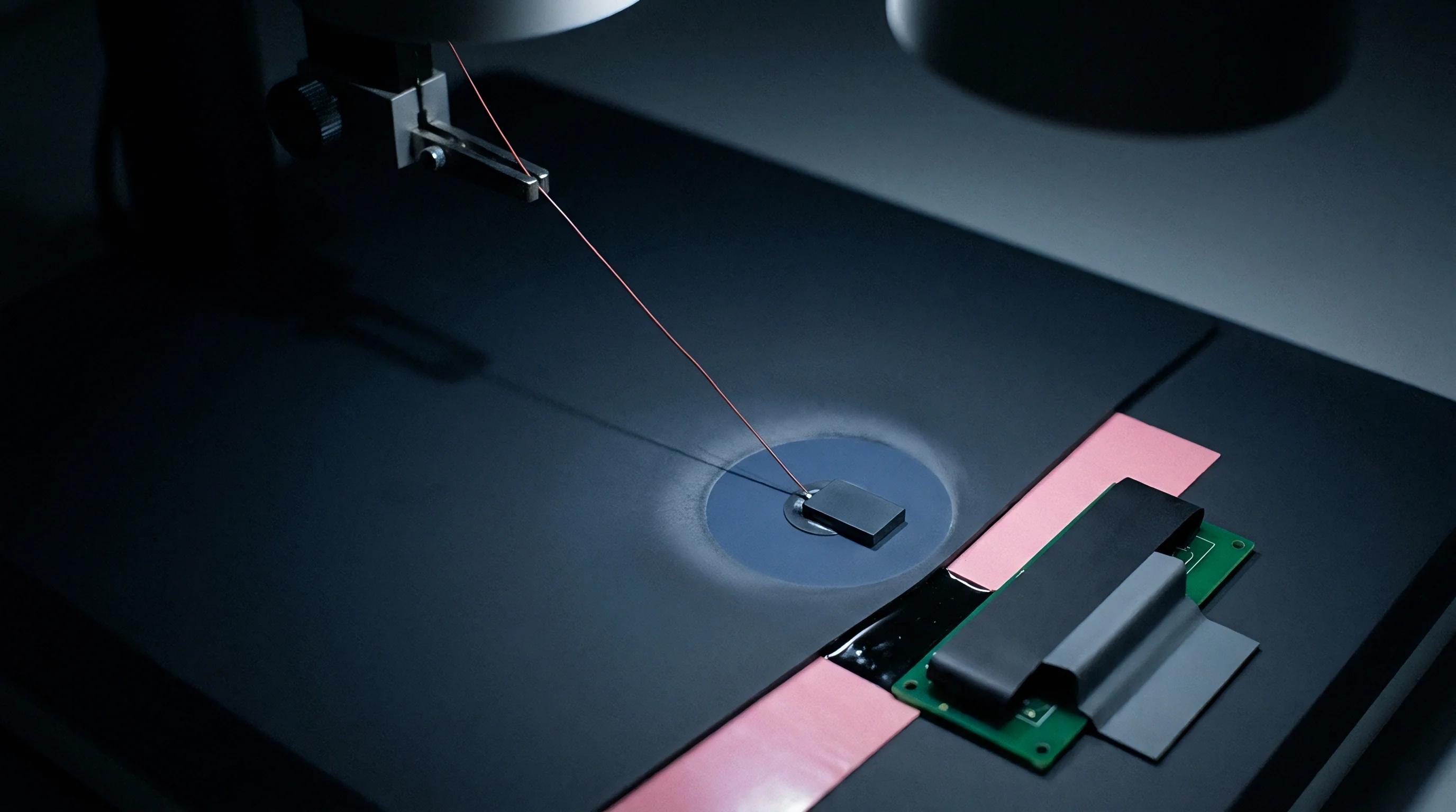
Strain
Mechanical deformation across a printed circuit substrate transfers parasitic stress directly into encapsulated silicon dies. Micro-electromechanical systems (MEMS) pressure sensors, accelerometers, and optical elements experience zero-point calibration shifts when board bending, thermal expansion mismatch, or package mounting torque forces mechanical displacement into the active sensing region. Package selection governs how effectively a device isolates its internal die from external physical loads.

Thermomechanical Strain Transfer to Sensor Elements
Differences in thermal expansion coefficients between epoxy molding compounds, FR-4 substrates, and silicon crystals create zero-point bias shifts. Standard FR-4 exhibits an in-plane thermal expansion coefficient of 14 to 17 ppm/°C, whereas silicon expands at approximately 2.6 ppm/°C. During thermal cycling from -40 °C to 85 °C, this expansion differential induces shear stresses across the solder joint matrix, where copper thickness further influences dissipation. Molded plastic DFN packages transfer substrate stress directly into the die attachment gel, altering internal piezoresistive offsets by up to 1.5 percent over operational lifespans.
Cavity-type LGA packages place the silicon element inside an open or gel-filled pocket, separating the top surface from rigid epoxy encapsulation. Gel-filled cavities absorb mechanical shear while transmitting hydrostatic pressure, suppressing stress-induced drift by a factor of four compared to fully overmolded packages. Solder joint fatigue life decreases exponentially as package footprint length increases, making smaller footprints inherently more resilient against thermal stress cycling.
Placing piezoresistive sensor elements adjacent to mechanical board fasteners couples assembly torque directly into offset voltage drift.

Structural Isolation and PCB Cutout Mechanics
Milling physical slots around sensitive silicon components decouples localized substrate bending from internal sensing microstructures. A U-shaped or H-shaped isolation slot routed through the PCB around a discrete LGA footprint redirects structural flexure around the device. Mechanical isolation slots reduce strain transfer by up to 80 percent, permitting precise optical or inertial measurements on thin 0.8 mm boards subjected to torsional loads.
Implementation of board cutouts introduces tradeoffs in available trace routing area and assembly cleanliness. Dust, wash fluid, and conformal coatings migrate through routed slots unless masked during processing. Board designers place isolation slots at a minimum distance of 1.5 mm from component pads to prevent solder mask cracking during panel singulation using routing bits or laser cutters.
Anchoring sensor land patterns away from structural mounting holes and board edges reduces strain coupling into sensitive internal elements.


Interface
Selecting a signal communication methodology establishes the physical component count and wiring footprint surrounding a primary silicon device. Modern discrete sensors offer digital interfaces such as Inter-Integrated Circuit (I2C) and Serial Peripheral Interface (SPI), alongside traditional ratiometric analog outputs. Choosing an interface dictates not only trace routing density but also passive component count, host microcontroller pin allocation, and firmware timing overhead.

Electrical Interconnect Overhead across Bus Topologies
Serial communication protocols impose distinct physical circuit requirements that alter local board space allocation. An I2C bus utilizes two shared lines, Serial Data (SDA) and Serial Clock (SCL), requiring pull-up resistors to the supply rail. Resistor package footprint selection directly impacts net board area.
Utilizing 0402 discrete pull-up resistors adds 1.0 mm² per line, while 0201 packages consume 0.3 mm² per line. Trace length introduces parasitic capacitance. Bus capacitance limits of 400 pF for standard and fast-mode I2C restrict total trace length and connected device counts.
SPI configuration eliminates passive pull-up resistors on signal lines but demands four dedicated traces: Master Out Slave In (MOSI), Master In Slave Out (MISO), Serial Clock (SCLK), and Chip Select (CS). SPI trace routing requires clear layout channels, especially when multiple discrete devices sit on the same board. Analog ratiometric outputs require dedicated low-pass RC filtering networks and precision voltage references, adding up to four passive components per sensor channel and occupying up to 15 mm² of board area.
I2C bus architectures exchange trace count reduction for passive pull-up component placement and clock stretching delays in host controller firmware.
Comparing interface options clarifies total component count, trace footprint, and firmware complexity across implementation architectures.
| Interface Standard | Trace Count | External Passives | Passive Footprint Area (mm²) | Max Bus Length (cm) | Firmware Driver Overhead |
|---|---|---|---|---|---|
| I2C Standard / Fast | 2 | 2 Pull-up Resistors | 0.6 to 2.0 | 30 | Low (Hardware Peripheral) |
| I2C High-Speed | 2 | 2 Active Pull-ups | 2.5 to 4.0 | 15 | Medium (Timing Critical) |
| SPI 4-Wire | 4 | 1 Decoupling Cap | 0.3 to 1.0 | 50 | Low (Simple Register Access) |
| SPI 3-Wire | 3 | 1 Decoupling Cap | 0.3 to 1.0 | 40 | Medium (Half-Duplex Handling) |
| Analog Ratiometric | 1 to 3 | 3 Filters / Caps | 3.0 to 8.0 | 100 | High (ADC Calibration / Sampling) |

Should System Designers Select SPI over I2C for Small Footprint Applications?
High-speed data transfer needs frequently clash with available trace routing space on dense two-layer assemblies. SPI protocols achieve clock rates exceeding 20 MHz, permitting rapid burst readouts that return host microcontrollers to low-power sleep modes quickly. Routing four high-speed SPI signal traces under controlled-impedance constraints demands significant top-layer copper width, forcing layout compromises near board edges.
I2C bus designs limit data rates to 400 kHz or 3.4 MHz in high-speed mode, but they allow daisy-chaining multiple sensors onto a single two-wire bus. This shared topology drastically reduces microcontroller pin count requirements, allowing smaller host MCU packages. Firmware developers write polling routines or manage interrupt lines to process data, trading bus wiring area for software execution time.
High pull-up resistance values can satisfy bus speed requirements on paper while omitting the parasitic capacitance introduced by dense multilayer board routing.


Assembly
Surface-mount placement yields depend heavily on matching stencil geometry to component termination profiles. Micro-sized LGA, DFN, and WLCSP packages introduce strict solder paste printing parameters. Misalignment between stencil apertures and copper land patterns produces solder bridging, tombstoning, or voiding under central thermal and ground pads.
Package volume selection drives line yield rates and post-reflow inspection procedures.

Surface Mount Assembly Tolerances and Defect Profiles
High-volume manufacturing lines hit strict yield limits when solder paste deposition volumes fluctuate across fine-pitch pads. Stencil thickness selection balances the volume requirements of large passive components against fine-pitch sensor terminations. Standard 0.12 mm laser-cut stainless steel stencils accommodate 0.5 mm pitch LGA packages but supply excessive solder paste to 0.4 mm pitch WLCSP devices, resulting in solder bridges beneath the die.
Automated pick-and-place equipment achieves alignment tolerances within ±0.03 mm for high-speed optics. Placement deviations exceeding 0.05 mm cause asymmetric surface tension forces during reflow, pulling lightweight DFN components off-center. Solder voids beneath exposed center pads reduce thermal conductivity and create mechanical imbalances that translate into sensor signal distortion.
IPC-A-610 standards specify maximum thermal pad voiding thresholds of 25 percent for high-reliability assemblies.
JEDEC J-STD-020 standard reflow peak temperature limits dictate that Level 3 moisture-sensitive sensor packages exposed to ambient factory humidity for over 168 hours suffer internal package delamination during convection soldering.
Qualifying stencil apertures and solder reflow parameters requires following systematic verification steps to maintain yield figures above 99.5 percent.
- Calculate the stencil aperture area ratio by dividing the pad surface area by the aperture side-wall area, ensuring values exceed 0.66 for clean paste release.
- Select Type 4 or Type 5 solder paste powder sizes when pad pitch drops below 0.4 mm to ensure consistent volume deposition through micro-apertures.
- Apply rounded rectangle or oblong aperture geometries with a 10 percent area reduction relative to copper pads to mitigate solder bead formation.
- Establish a convection reflow profile featuring a soak zone between 150 °C and 180 °C for 90 seconds to equalize thermal mass across the board.
- Perform automated X-ray inspection (AXI) on initial production samples to quantify void percentages under bottom-terminated pads.

Worked Reliability Comparison across Package Form Factors
Consider a baseline automotive environmental sensing module manufactured at a production run of 100,000 units annually. Assume a target assembly defect yield threshold below 50 dppm. The evaluation compares three discrete package implementations using published assembly line metrics: a WLCSP-6 (1.2 x 0.8 mm, 0.35 mm pitch), an LGA-12 (2.5 x 3.0 mm, 0.5 mm pitch), and a populated SMT module (12 x 12 mm, 2.54 mm pitch castellations).
Calculations assume standard Type 4 SAC305 solder paste, a 0.10 mm stencil for WLCSP, and a 0.127 mm stencil for LGA and module configurations. First-pass yield modeling incorporates placement accuracy, stencil clogging probability, and reflow bridging rates.
The WLCSP-6 configuration registers a baseline defect rate of 120 dppm, predominantly caused by micro-bridging and solder balling beneath the ultra-fine pitch pads. Reworking defective WLCSP devices requires specialized hot-gas stations and micro-scopes, costing $8.50 per reworked unit. Total annual rework expenditure for WLCSP assembly reaches $1,020 across the 100,000 unit run.
The LGA-12 configuration demonstrates a defect rate of 25 dppm, well within the target performance boundary. Standard optical inspection identifies misaligned components, and automated hot-air rework procedures fix boards at $3.20 per unit. Annual LGA rework expenditure totals $80.
The populated SMT module shows a 5 dppm defect rate due to large castellations, but its raw component unit cost is significantly higher.
IPC J-STD-001 Class 3 inspection criteria specify zero acceptable micro-cracking in bottom-terminated sensor solder fillets, forcing assembly lines to reject boards with insufficient toe fillet protrusion.

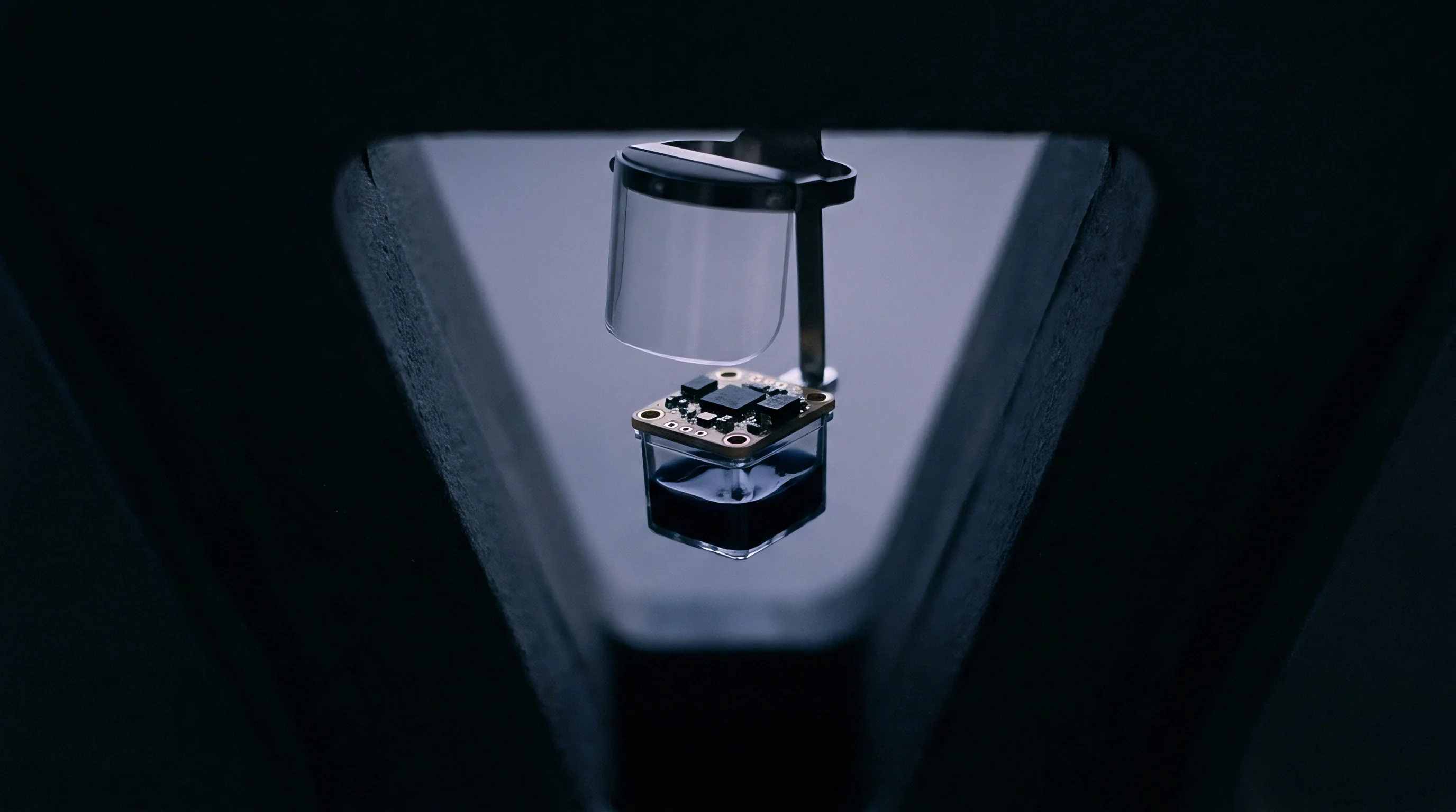
Economics
Financial calculations for discrete silicon integration extend beyond baseline bill-of-materials costs. Purchasing raw silicon in WLCSP or DFN packages provides low component unit pricing, yet total landed expenses must include NRE tooling, PCB layer count additions, assembly yield loss, and test firmware development. Conversely, pre-calibrated populated sensor modules carry high unit acquisition prices but eliminate internal engineering work and specialized production equipment.

Total Landed Cost Modeling across Integration Variants
Evaluating direct silicon purchasing costs alongside assembly expenditures establishes the net financial baseline for hardware platforms. Bare LGA devices sell at high volumes for $0.45 to $1.20 per unit. Integrating these discrete devices requires adding decoupling capacitors, pull-up resistors, precision reference ICs, and allocating board space.
Component placement fees at SMT assembly houses average $0.015 to $0.03 per placement, adding $0.09 to the assembly cost of a discrete sensor circuit containing three passives.
Module variants integrate the sensing element, ASIC signal conditioner, passive network, and protective lid into a pre-calibrated assembly priced from $3.50 to $8.00 per unit. Modules eliminate internal calibration software development and factory test station overhead, saving up to $50,000 in upfront engineering setup expenses. The landed cost decision hinges on production scale: low-volume runs favor modules, while high-volume platforms justify discrete package integration.
Comprehensive cost evaluation requires comparing acquisition, manufacturing, and operational expenses across all physical variants.
| Integration Attribute | Bare Die / WLCSP | Discrete LGA / DFN | Populated SMT Module | Cabled External Probe |
|---|---|---|---|---|
| Unit Price (100k Volume) | $0.35 – $0.70 | $0.50 – $1.20 | $3.50 – $6.50 | $12.00 – $25.00 |
| PCB Layer Requirement | 6-Layer HDI | 4-Layer Standard | 2-Layer Standard | 2-Layer Standard |
| Passive Component Overhead | 3 to 5 Passives | 2 to 4 Passives | Zero Integrated | Zero Integrated |
| Calibration Cost per Unit | $0.15 (In-Factory) | $0.15 (In-Factory) | $0.00 (Pre-Calibrated) | $0.00 (Pre-Calibrated) |
| Minimum Order Quantity | 5,000 (Tape & Reel) | 3,000 (Tape & Reel) | 500 (Trays) | 100 (Boxed) |
| Firmware Development Time | 4 to 6 Weeks | 3 to 4 Weeks | 1 to 2 Weeks | 1 Week |

Volume Thresholds for In-House Surface Mounting
Capital expenditure recovery for automated pick-and-place infrastructure relies on unit throughput scale. Calculating the financial break-even point between purchasing integrated sensor modules and placing discrete LGA devices involves balancing fixed NRE expenses against variable unit cost savings.
Assuming an NRE allocation of $30,000 for HDI board layout, stencil design, calibration software, and test fixture setup, moving from a $4.50 integrated module to a $0.85 discrete LGA package yields a net unit saving of $3.65. Accounting for a $0.15 per unit factory calibration expense and $0.09 in placement fees reduces net unit savings to $3.41.
Whether custom module encapsulation offsets the long-term risk of discrete package component obsolescence remains an open commercial question for low-volume industrial platforms.