Solid State Switch Charge Injection Limits in Wideband Electrometer Operational Amplifier Networks
Wideband electrometer networks limit solid state switch charge injection below 50 fC using complementary switch gating and bandwidth-matched compensation.


Gate
Semiconductor switching elements in ultra-high impedance transimpedance loops introduce unwanted parasitic charge transfers during digital state transitions. In wideband electrometer operational amplifier networks, the summing junction sits at virtual ground while presenting input impedances exceeding tens of gigaohms. When an analog switch attached to this node transitions between on and off states, mobile charge carriers within the semiconductor channel exit through the terminal drain and source regions.
A significant fraction of this channel charge dumps into the amplifier summing node, shifting the input node voltage away from virtual ground.
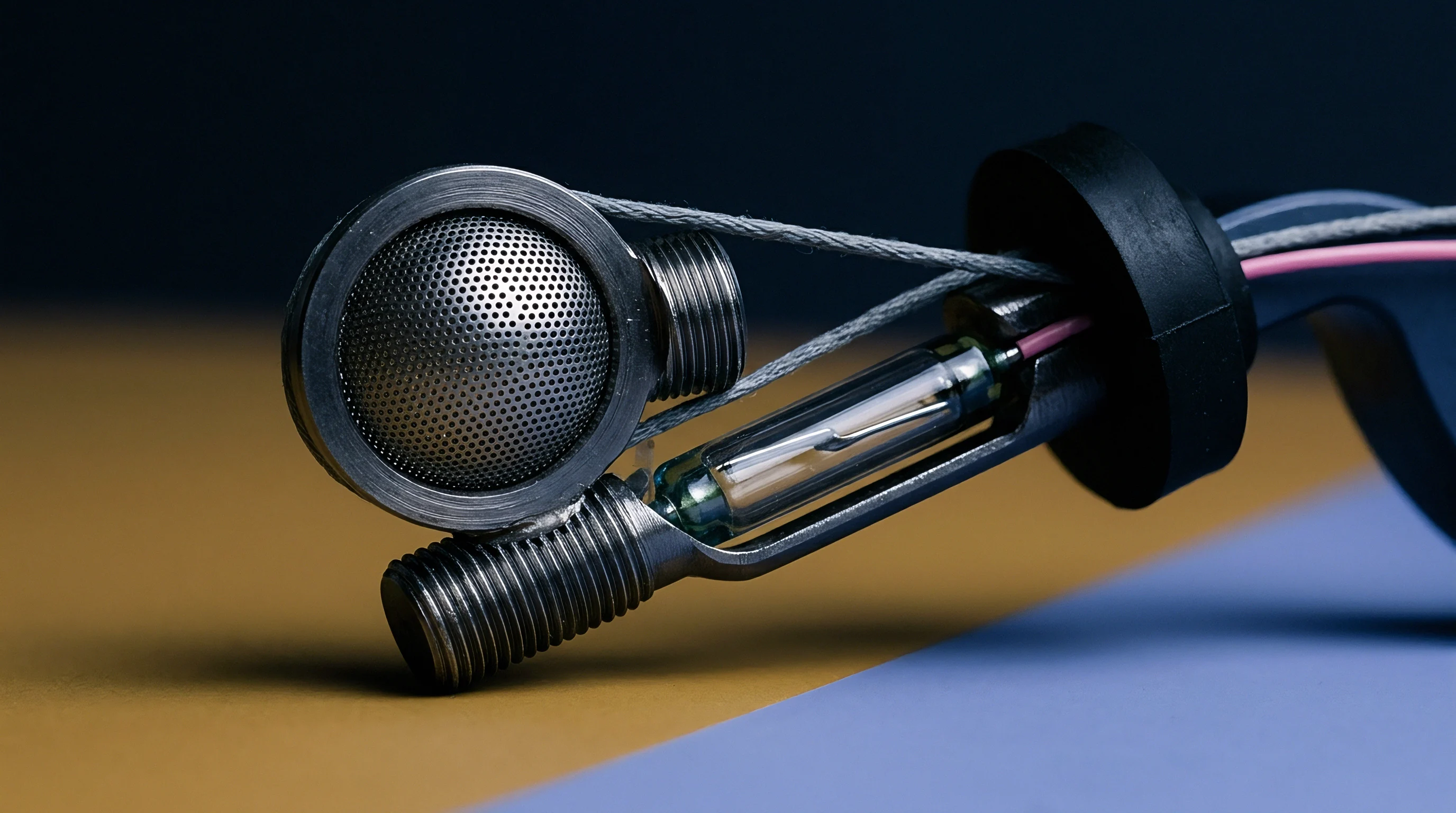
Semiconductor Channel Physics and Carrier Displacement
Charge migration inside a metal-oxide-semiconductor field-effect transistor originates from the physical displacement of mobile carriers when the control voltage swings between logic states. In an N-channel MOSFET switch operating in the triode region, the total inversion layer channel charge scales directly with gate oxide capacitance, channel surface area, and gate-to-source overdrive voltage. Expressed analytically, total channel charge equals gate width multiplied by channel length, oxide capacitance per unit area, and the difference between gate-source voltage and threshold voltage.
When the control gate voltage transitions below the threshold level to turn the switch off, the inversion channel collapses. Charge transfer shifts node voltage. Mobile electrons migrate toward the source and drain terminals based on terminal impedances and the clock edge transition time.
In rapid switching regimes where clock edge fall time is significantly shorter than the channel RC time constant, channel charge splits equally between drain and source terminals. In slow switching regimes where clock fall time exceeds the internal channel diffusion delay, charge flows preferentially toward the low-impedance terminal, altering the net carrier count delivered into the high-impedance electrometer input.

Parasitic Capacitance Mechanisms in CMOS Switches
Overlapping gate metal and diffusion regions create intrinsic capacitance components across internal node boundaries. Gate-to-drain overlap capacitance and gate-to-source overlap capacitance act as direct electrostatic coupling paths between the digital control driver and the sensitive analog signal path. Gate overlap capacitance dominates total charge transfer.
Even when the transistor channel is entirely depleted, control voltage swings feed directly through these parasitic overlap capacitors via pure displacement current.
Complementary Metal-Oxide-Semiconductor switches combine parallel N-channel and P-channel transistors to pass rail-to-rail analog signals. While N-channel channel charge consists of mobile electrons, P-channel channel charge consists of mobile holes driven by an opposite polarity control pulse. Parasitic capacitance scales with die surface area.
Gate overlap capacitance in P-channel devices typically exceeds that of N-channel devices due to lower hole mobility demanding wider transistor geometries to achieve equivalent on-resistance. Consequently, the opposite-polarity gate transitions of a CMOS transmission gate never cancel perfectly in physical silicon, leaving a net residual charge injection step at the transimpedance summing junction.
Whether third-generation silicon-on-insulator switch geometries can reduce sub-picofarad gate capacitance without increasing drain off-resistance remains an unresolved question for sub-femtoampere electrometer design.


Injection
The magnitude of pulse displacement delivered into a high-impedance node scales directly with control signal slope and parasitic coupling capacitance. In a wideband electrometer network operating with sub-picopicoampere current sensitivity, a switch charge injection of one picocoulomb drives a ten-picofarad feedback integration capacitor by one hundred millivolts. This instant offset shift forces the operational amplifier output away from its linear operational point, consuming available headroom and introducing measurement error.

Charge Transfer Dynamics across Solid State Technologies
Solid-state switching components exhibit variable charge coupling depending on substrate isolation, drive gate amplitude, and semiconductor layout structure. Discrete Junction Field-Effect Transistors, monolithic CMOS analog switches, and photo-coupled MOSFET relays present vastly different parasitic transfer metrics when evaluated under identical electrometer operating conditions.
| Switch Technology | Charge Injection (pC) | Off-State Leakage (pA) | On-Resistance (Ohms) | Turn-On Time (ns) |
|---|---|---|---|---|
| Standard CMOS (Monolithic) | 3.5 to 10.0 | 1.0 to 10.0 | 35 to 120 | 15 to 40 |
| Silicon-on-Insulator CMOS | 0.2 to 0.8 | 0.1 to 1.0 | 120 to 250 | 8 to 20 |
| Discrete N-Channel JFET | 0.05 to 0.3 | 0.01 to 0.1 | 100 to 300 | 5 to 15 |
| Optically Coupled Photo-FET | 0.5 to 2.0 | 0.005 to 0.05 | 500 to 2000 | 100000 to 500000 |
Off-state leakage current dictates steady-state accuracy, whereas charge injection governs transient recovery kinetics. Discrete JFET switches deliver tiny charge transfer figures because the gate-channel junction consists of a small-area reverse-biased PN junction rather than an extensive oxide layer. Optically coupled relays completely eliminate digital gate drive capacitive coupling by utilizing photon transport across an insulating barrier, though their slow switching speed limits use in wideband applications.
Minimizing control gate drive voltage amplitude reduces total channel charge injection proportionally without altering switch on-state resistance.

Femto-Coulomb Measurement Methods on the Bench
Accurate quantification of sub-picocoulomb switching transients relies on integrating amplifiers configured with low-drift polystyrene integration capacitors. Standard oscilloscope probes introduce ten picofarads of parasitic capacitance and megaohm shunt loading, completely swamping the high-impedance electrometer summing node. Bench characterization utilizes a high-gain transimpedance stage whose output voltage step is recorded on a high-speed digital storage oscilloscope following a switch toggle event.
Primary charge transfer pathways within solid-state electrometer switch nodes originate from specific physical coupling mechanisms:
- Channel Displacement Current driven by mobile electron or hole evacuation out of the conducting region during gate pinch-off transitions.
- Gate Overlap Capacitive Coupling propagating steep control signal edges directly through oxide overlap capacitance into terminal nodes.
- Substrate Junction Capacitance coupling voltage transients from bulk silicon substrates through reverse-biased isolation diodes into drain structures.
- Package Lead Parasitic Coupling cross-coupling logic drive pin lines into adjacent sensitive analog input pins via inter-lead trace capacitance.
Switching speed impacts transient magnitude. When driving switches in femtoampere electrometer loops, shaping gate control signal edges with controlled RC slew rates suppresses high-frequency displacement current spikes without extending low-impedance conduction state delays beyond circuit requirements.
Designing control voltage drivers with matching turn-on and turn-off slew rates minimizes net charge residual at the inverting summer.


Symmetry
Differential charge cancellation employs complementary switching topologies to neutralize channel-displaced carriers at the summing junction. By placing a secondary dummy switch or dummy capacitor driven by an inverted clock phase in parallel with the primary analog switch, equal and opposite charge pulses combine at the node to produce zero net offset shift.

Calculated Charge Cancellation in Integrator Reset Loops
Designing a high-speed electrometer network demands quantitative evaluation of both primary switch charge injection and compensating dummy switch charge offset. A worked scenario illustrates the baseline mechanics and residual limits of charge steering compensation.
Assume a wideband transimpedance integrator configured with a feedback capacitor C_f of 10 pF, driven by an operational amplifier exhibiting a 500 MHz gain-bandwidth product. The integrator reset function uses a monolithic N-channel MOSFET switch driven by a 0 V to 3.3 V gate control pulse. Datasheet extraction and bench verification establish a primary switch gate-to-drain overlap capacitance C_gd of 0.45 pF and an active channel inversion charge Q_ch of 0.60 pC at an overdrive voltage of 3.3 V. Assuming fast switching logic where channel charge splits evenly between drain and source, total charge injected into the summing node Q_in during a turn-off event equals:
Q_in = (0.5 Q_ch) + (C_gd Delta V_gate)
Q_in = (0.5 0.60 pC) + (0.45 pF 3.3 V) = 0.30 pC + 1.485 pC = 1.785 pC
This 1.785 pC charge injection step into the 10 pF feedback capacitor generates an immediate output voltage offset step Delta V_out across the amplifier:
Delta V_out = Q_in / C_f = 1.785 pC / 10 pF = 178.5 mV
To compensate for this voltage step, a dummy N-channel switch with source and drain shorted together is added to the summing node and driven by an inverted logic signal swinging from 3.3 V to 0 V. The dummy switch gate area is sized at exactly half the primary switch area, yielding a total dummy capacitance C_dummy of 0.45 pF. When the primary switch turns off, the dummy switch turns on, drawing charge away from the summing node. Assuming a manufacturing gate area mismatch tolerance of 3 percent between primary and dummy structures, the net residual charge Q_net remaining on the summing node becomes:
Q_net = Q_in – Q_dummy = 1.785 pC – (0.97 1.785 pC) = 0.05355 pC = 53.55 fC
With dummy switch compensation active, the residual output voltage step drops significantly:
Delta V_out_compensated = 53.55 fC / 10 pF = 5.355 mV
At a control swing of 3.3 V and ambient temperature of 25 degrees Celsius, CMOS switch charge injection introduces a 1.2 pC displacement into the summing node.
Residual offset step reduction from 178.5 mV down to 5.355 mV preserves amplifier dynamic range and prevents input stage clipping. Lower gate drive amplitude reduces channel charge. However, clock phase skew between true and inverted control signals introduces temporal mismatch during the switching transition.
If the inverted clock edge lags the primary clock edge by 500 picoseconds, an uncompensated charge spike of 1.785 pC exists at the summing junction for that half-nanosecond window, exciting high-frequency ringing in wideband op-amps.
Improper matching of control signal timing in dummy switch networks drives the operational amplifier into hard rail saturation, causing prolonged recovery delays and severe data corruption during high-speed sampling.

Settling
Amplifier recovery from transient voltage swings depends on open-loop phase margin, slew rate limits, and feedback network pole locations. When charge injection forces a voltage step onto the inverting input of an electrometer operational amplifier, the closed-loop feedback network acts to restore the virtual ground state. The time required for the amplifier output to settle within a tight error band depends on loop response dynamics.

Does Differential Switch Topology Mitigate Dynamic Op-Amp Saturation?
Splitting the control pulse into complementary phases reduces the peak magnitude of the transient voltage pulse appearing at the inverting node. When a single-ended switch injects several picocoulombs into a low-capacitance summing node, local node voltage momentarily leaps away from ground. If this excursion exceeds the input differential linear range of the operational amplifier, the input stage enters non-linear saturation.
During input stage saturation, internal transconductance drops to zero, and the amplifier slew rate limits. Transimpedance feedback loops cease linear regulation until internal bias nodes recover. Differential dummy switches limit the instantaneous voltage excursion to a few millivolts, keeping the operational amplifier input stage firmly within its small-signal linear operating region and preventing slew-rate limited overload conditions.

Feedback RC Constants and Overload Recovery
When a switching pulse drives the summing node beyond the amplifier input stage linear range, internal gain stages saturate and suspend normal transimpedance action. Dynamic settling performance across various high-speed electrometer amplifiers highlights how open-loop bandwidth and switch injection magnitude govern recovery speed.
| Op-Amp Topology | Gain Bandwidth (MHz) | Slew Rate (V/us) | Injected Charge (pC) | Peak Node Excursion (mV) | Settling Time to 0.01% (ns) |
|---|---|---|---|---|---|
| FET-Input Precision Stage | 16 | 60 | 2.5 | 250 | 1450 |
| Wideband Decompensated FET | 145 | 180 | 2.5 | 250 | 380 |
| Ultra-Wideband CMOS Stage | 500 | 950 | 2.5 | 250 | 85 |
| Ultra-Wideband CMOS Stage | 500 | 950 | 0.05 (Compensated) | 5 | 12 |
Amplifier saturation delays active measurement. Higher bandwidth amplifies high-frequency transient spikes. Transimpedance networks operating with high feedback resistor values introduce secondary poles with parasitic node capacitance, forming slow-settling exponential tails.
Dielectric absorption in printed circuit board substrates creates exponential long-tail voltage recovery following a switching transient. The interaction between amplifier open-loop output impedance and capacitive switch loading can degrade phase margin, triggering high-frequency ringing following switch state changes.
Factors degrading wideband electrometer settling timing include several parasitic layout interactions:
- Excessive Feedback Summing Node Capacitance lowering loop transmission crossover frequency and deteriorating system phase margin.
- Uncompensated Clock Skew Transients generating high-amplitude differential voltage spikes that drive input differential pairs into non-linear conduction.
- Substrate Dielectric Relaxation inducing low-frequency current redistribution tails across printed circuit board insulation layers.
- High Transimpedance Feedback Resistance interacting with switch off-state capacitance to create long time-constant real poles.
Switch vendors frequently state that quoted charge injection figures represent typical package averages under 50 ohm load conditions rather than ultra-high impedance electrometer operating environments.


Error
Systematic measurement offsets accumulate through the interplay of bias current, parasitic leakages, and switching transients. In low-current instrumentation processing femtoampere signals, total error equals steady-state DC leakage plus the time-averaged AC equivalent current generated by periodic switch toggling. Operating an analog switch at a high switching frequency transforms discrete charge injection pulses into a continuous offset current equivalent to charge injection multiplied by switching frequency.

Summing Node Parasitic Budgeting
High-frequency electrometer networks require tight bounds on board trace capacitance and dielectric losses to prevent bandwidth attenuation. Trace routing at the summing junction demands minimal physical surface area to suppress ambient capacitive noise pickup. Guard rings divert surface leakage currents.
Surrounding sensitive switch signal traces with driven guard traces held at virtual ground potential redirects surface leakage currents away from the measuring node.
Adherence to IEC 60068-2-78 humidity exposure standards prevents moisture-induced surface insulation breakdown across electrometer guard traces.
Layout spacing alters parasitic stray capacitance. Dry air enclosure suppresses surface contamination. Printed circuit board materials require careful selection.
FR-4 glass-epoxy laminates exhibit substantial dielectric absorption, storing residual charge during voltage transients and slowly bleeding carriers back into the node over several milliseconds. High-performance electrometer layouts mandate polytetrafluoroethylene, alumina ceramic, or hydrocarbon ceramic substrate materials to guarantee clean transient response.

Environmental Influence on Sub-Picopicoampere Nodes
Ambient relative humidity exceeding forty percent induces surface conduction paths across epoxy IC packages, masking subtle switching charge artifacts. Thermal gradients generate unwanted thermoelectric voltages. Temperature fluctuations alter semiconductor switch off-state leakage exponentially, doubling leakage current for every eight-degree Celsius temperature rise in standard CMOS processes.
Systematic qualification of low-injection switch circuits requires a precise bench screening sequence:
- Isolate the electrometer board inside a Faraday enclosure to block external electrostatic interference.
- Bake the circuit assembly at 85 degrees Celsius for four hours to eliminate moisture trapped within package epoxy resin.
- Apply continuous DC supply voltages and verify baseline input bias currents using an automated electrometer meter stage.
- Inject controlled clock switching pulses into the switch gate terminal while monitoring transimpedance amplifier output on a wideband oscilloscope.
- Measure baseline voltage step amplitude Delta V at time t equals zero immediately following clock transition.
- Calculate net transferred charge Q by multiplying measured step amplitude Delta V by total calibrated summing node capacitance.
- Record long-term baseline drift over a ten-second observation window to identify dielectric absorption tail artifacts.
Compliance with IEC 61326-1 Clause 6.2 demands that signal conditioning networks maintain specified measurement accuracy within defined electromagnetic disturbance thresholds, forcing designers to shield sensitive switch gate drive traces.


Trade
Selecting high-speed analog switch components requires balancing parasitic channel charge against off-state leakage resistance and IC package lead coupling. Ultra-low charge injection components frequently exhibit higher on-state resistance or enlarged package footprints. Conversely, low on-resistance switches demand larger transistor gate geometries, which directly increases parasitic overlap capacitance and total injected charge.

Discrete Junction Field-Effect Transistors versus Monolithic Switches
Custom electrometer designs frequently evaluate discrete JFET devices alongside integrated CMOS analog switches to optimize node leakage. Discrete N-channel JFETs, such as 2N4117A variants, feature reverse-biased gate junction leakages below 10 fA at room temperature and low gate capacitance under 1 pF. However, discrete implementations require custom level-shifting gate drive circuits, expanding component count and printed circuit board surface area.
Monolithic CMOS switches provide integrated logic drivers, simplified power rails, and matched internal channels within small surface-mount packages. Silicon-on-insulator fabrication processes electrically isolate individual transistors using oxide dielectric trenches. Silicon-on-insulator substrates reduce substrate leakage.
SOI technology eliminates bulk substrate parasitic capacitance and reduces total charge injection below 0.5 pC while maintaining off-state leakages under 1 pA.
Dielectric absorption in printed circuit board substrates creates exponential long-tail voltage recovery following a switching transient.

Commercial Sourcing and Die Qualification Boundaries
Semiconductor supply chains offer specialized low-charge switch dies, yet commercial procurement cycles introduce batch-to-batch parasitic variation risks. Wafer fabrication lot variations cause gate oxide thickness and channel doping concentration fluctuations of up to fifteen percent across production runs. These process spreads alter gate overlap capacitance and threshold voltage, directly shifting net charge injection behavior.
Procurement specifications for high-reliability electrometer components must specify tight parameter windows for charge injection, off-leakage, and pin-to-pin parasitic capacitance under verified test conditions. Second-source qualification requires full dynamic bench evaluation, as generic functional equivalents often utilize alternate die layouts with elevated parasitic coupling.
System designers balancing sub-picocoulomb transient limits against 100 MHz bandwidth requirements select silicon-on-insulator structures while maintaining strict incoming wafer lot screening to guarantee reproducible channel parasitic parameters.