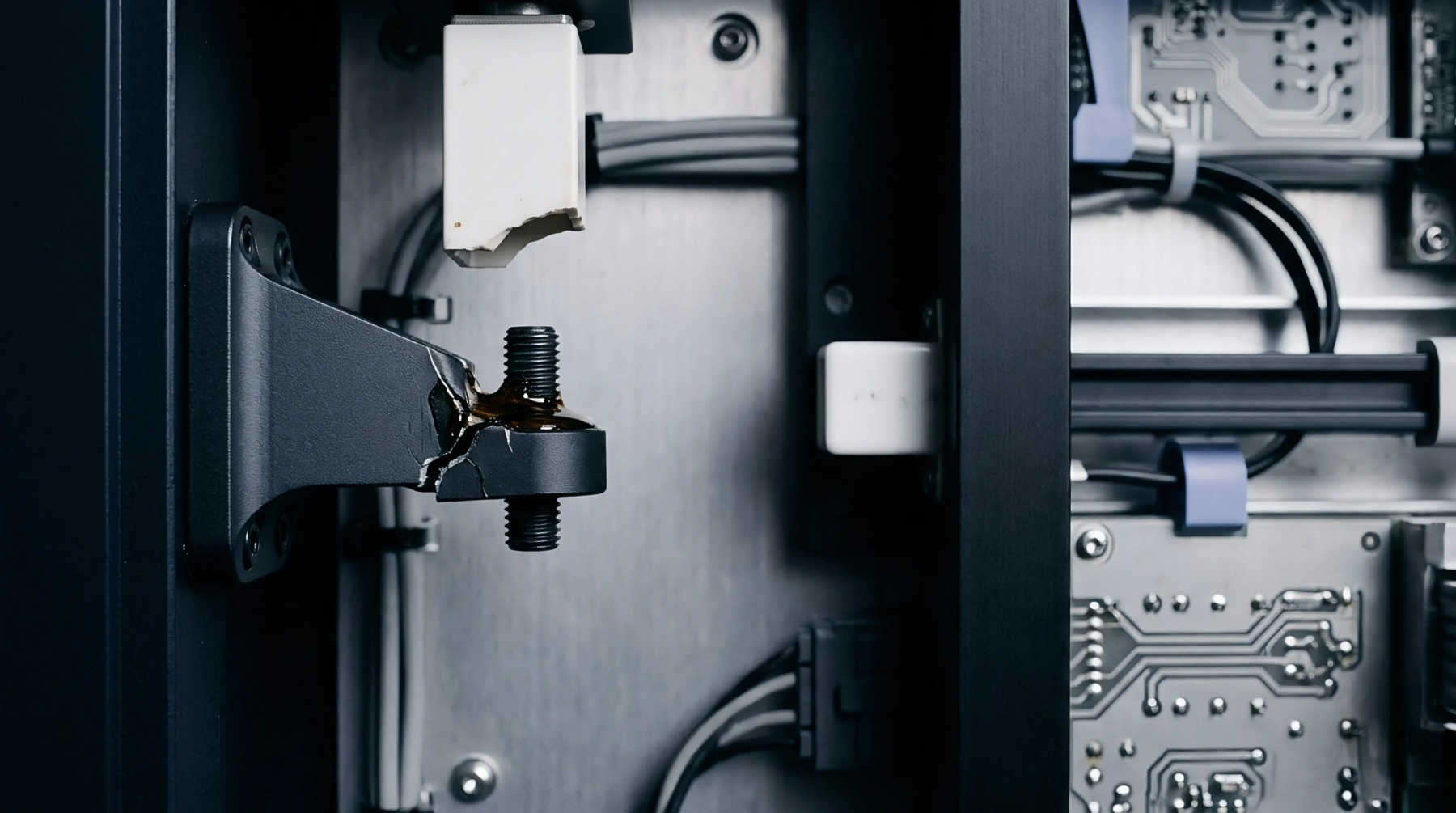
Thermomechanical Strain
Transient and residual structural forces generated across surface-mount sensor assemblies during thermal soldering cycles produce internal mechanical deformation. Significant reflow stress develops as printed circuit boards, solder pastes, component leads, and internal silicon structures expand and contract across temperature excursions reaching two hundred sixty degrees Celsius. Mismatches in coefficients of thermal expansion among these joining layers lock residual strain fields into the transducer package during cooling transitions.
The stress remains bounded by the plastic yield limits of the solder alloy and the viscoelastic relaxation capacity of the package substrate.
Transducer Distortion
Residual mechanical strain fields propagating into silicon sensing structures cause physical distortion of micromachined diaphragms and piezoresistive bridges. These internal shifts result in immediate zero-point baseline shifts and thermal sensitivity drifts, requiring post-assembly zero-offset trimming. In severe cases, rapid thermal gradients induce package warping that cracks fragile die-attach adhesive bonds or causes silicon die fracture.
Mechanical decoupling structures such as internal isolation pedestals or low-modulus silicones insulate active sensor membranes from these assembly-induced strain forces.
Soldering Window
Convection reflow thermal profiles must balance complete solder paste melting against package thermal endurance limits. Peak temperatures, liquidus dwell times, and cooling ramp rates dictate the final distribution of residual strain across the joint array. Rapid cooling profiles lock high dislocation densities and elastic strains into solder interconnects, elevating baseline drift rates during subsequent operational lifespans.
Controlled cooling rates around two to three degrees Celsius per second permit gradual stress relaxation without generating overly coarse solder intermetallic formations.
Verification Protocol
Instrument manufacturing facilities verify reflow survivability by subjecting populated test boards to consecutive simulated reflow profiles followed by continuous electrical monitoring. Transducer baseline stability, insulation resistance, and bridge balance are measured before and after reflow exposure to verify compliance with total allowable offset error limits. Optical profilometry maps board and package warpage across the heating profile to confirm that thermal distortion stays within flat-plane mounting tolerances.
Assemblies exceeding zero-offset drift boundaries are quarantined for destructive cross-sectioning and joint fatigue assessment.