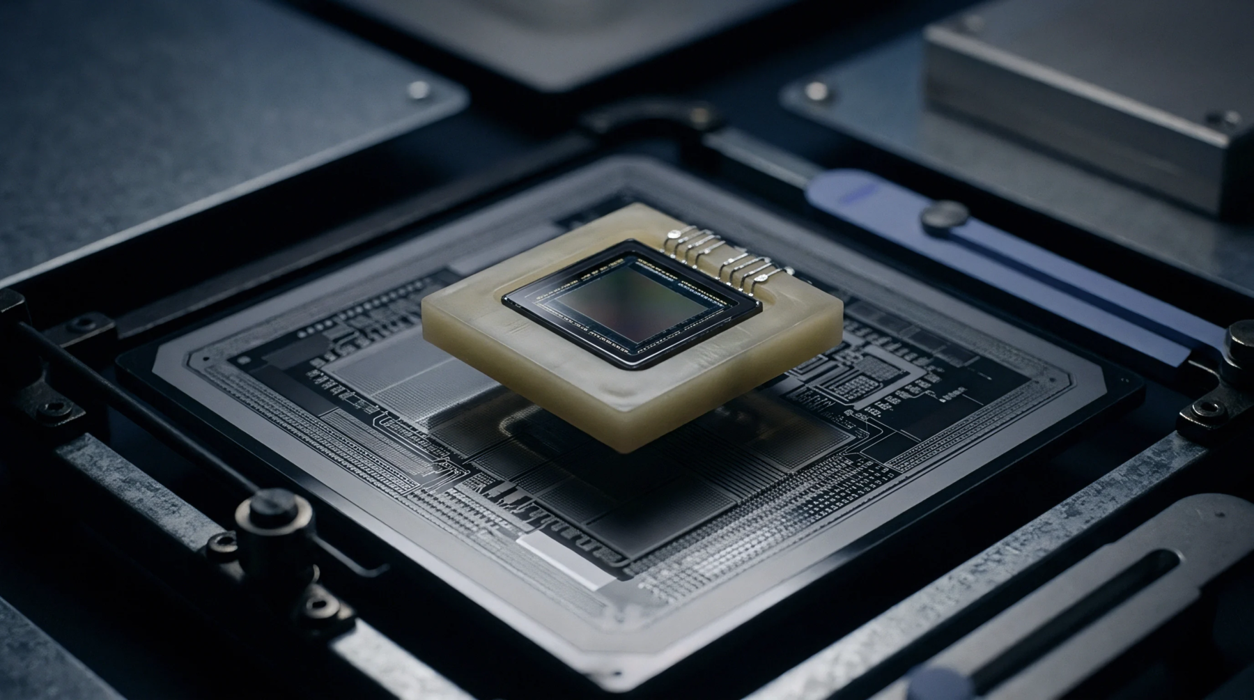
Geometry Domain
Physical geometric arrangements of conductive copper traces, ground planes and component mounting pads convert schematic circuit diagrams into physical circuit assemblies. Precision instrumentation hardware relies on printed circuit board layout to maintain low-noise signal integrity and minimize electromagnetic interference around sensitive analog sensors. Spatial design rules govern differential impedance matching, parasitic capacitance limits and current return paths.
Boundary conditions end where high-frequency parasitic transmission line effects require wave-guide or RF substrate design methodologies.
Ground Isolation
Unwanted ground loops introduce common-mode noise into microvolt-level sensor signal paths. Partitioning analog and digital ground regions in printed circuit board layout isolates sensitive front-end amplifiers from noisy digital switching currents. Single-point grounding or star ground topologies connect isolated ground planes at a single point near the analog-to-digital converter.
Trace Coupling
Parallel conductor traces create parasitic capacitive and inductive channels that couple high-frequency clock signals into sensitive measurement nodes. Proper trace separation and guard traces in printed circuit board layout attenuate cross-talk coupling between adjacent signal lines. Differential routing maintains equal trace length and symmetrical orientation to maximize common-mode noise rejection.
Thermal Balance
Asymmetric copper distribution creates localized thermal gradients that stress fragile MEMS packages and surface-mount sensors. Thermal symmetry rules enforce balanced copper fill around precision sensor footprints to prevent uneven heat dissipation. Automated design rule checks verify clearance distance, trace width tolerances and layer stackup specifications before board manufacturing.