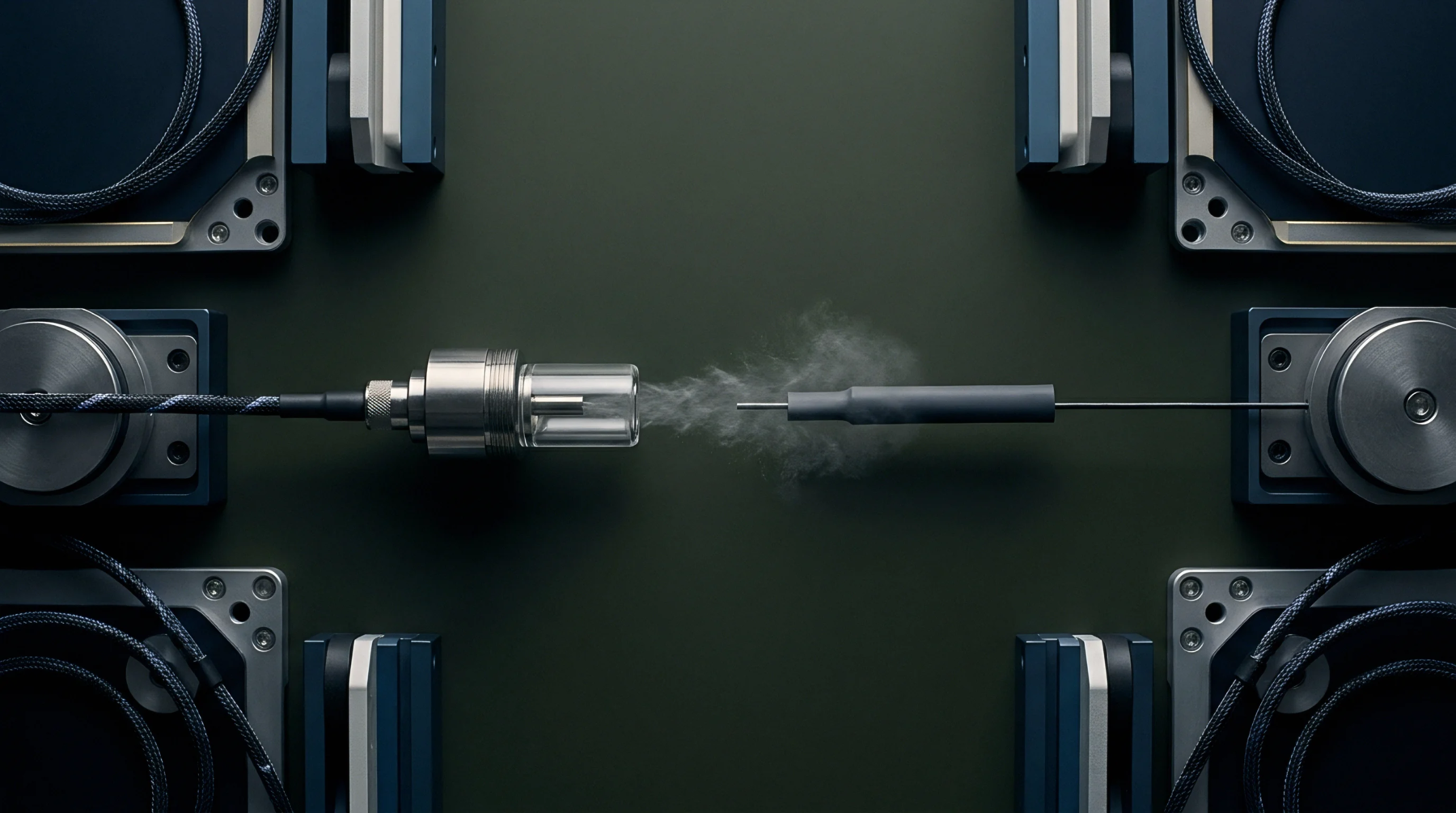
Attachment Force
Physical protection protocols minimize external conductor fatigue by distributing axial loads away from termination points. Mechanical strain relief prevents cable damage during operation through the application of clamping or molding geometries that grip the cable jacket. These barriers ensure that forces exerted on the external cable do not translate into electrical discontinuities at the contact interface.
Proper deployment maintains the integrity of the signal path under repetitive movement or static tension.
Installation Tolerance
Calibration of grip strength requires attention to the material properties of the conduit and the intended degree of movement. Engineers define the allowable pull force based on the tensile strength of the internal conductor and the insulation material. Testing at the manufacturing stage often involves applying a specified weight to the cable assembly to confirm that no movement occurs at the terminal connection.
Failure to meet these criteria results in early fatigue and eventual open circuits in the assembly. Variability in mounting surface friction coefficients often necessitates the use of locking hardware to preserve the calibrated state of the assembly.
Component Geometry
Designers utilize various physical forms such as rigid boots or spring assemblies to manage bending radii and limit sharp angles. Each form limits the curvature of the cable to prevent internal conductor breakage or dielectric degradation. Rigid structures provide a fixed transition that prevents micro-bending at the entrance of a connector housing.
Flexible designs allow for repeated angular displacement without placing excessive stress on the internal solder joints. High frequency applications demand specific impedance control which these geometries must support during the life of the connection.
Performance Verification
Metrological assessment confirms that tension management maintains consistent contact resistance across the expected operational range. Technicians verify the efficiency of the assembly by subjecting the connection to standardized pull tests while monitoring signal continuity with high precision instrumentation. Drift in contact resistance during these trials identifies an undersized or improperly seated grip.
Any displacement of the cable relative to the housing indicates an insufficient design margin. Reliable protection against mechanical loads provides the fundamental condition for long term signal stability in harsh environments.