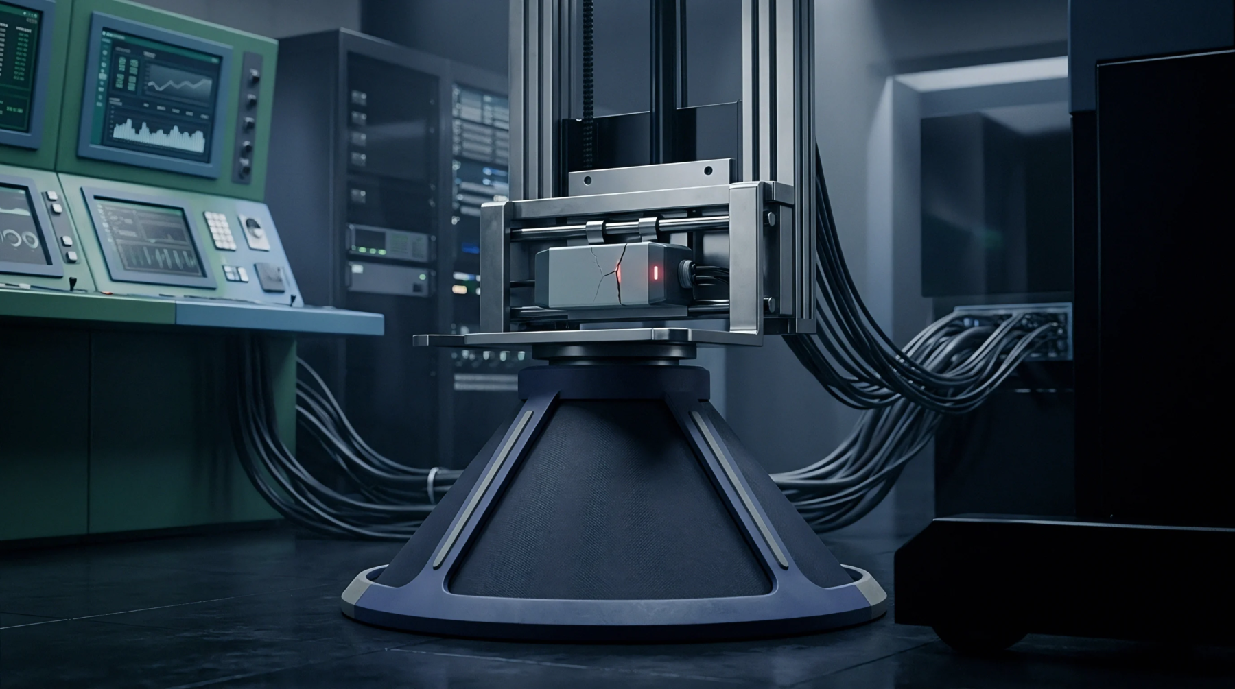
Displacement Transmission Mechanics
Energy transfer between an external flexible isolating boundary and an internal electromechanical transducer occurs via an incompressible fluid column that links structural deflection to electrical signal generation. In isolated pressure transmitters, hydro mechanical coupling establishes the kinematic and elastic interaction between the isolating diaphragm, the hydraulic fill fluid, and the primary sensing microchip. External pressure drives the flexible outer diaphragm, which displaces a defined liquid volume through internal conduits to deform a silicon, ceramic, or metallic piezoresistive element.
This coupled interaction fails to transfer pressure faithfully if fluid cavitation occurs under rapid vacuum conditions or if the containment boundary undergoes plastic deformation.
Stiffness Interdependence
The elastic response of the internal sensor diaphragm works in series with the outer barrier diaphragm, mediated by fluid volume conservation. If the outer barrier diaphragm possesses excessive mechanical stiffness compared to the sensing die, a substantial fraction of the applied process load is absorbed as internal stress within the barrier metal rather than transferring to the sensing element. Fluid passage geometry governs viscous damping across the coupling pathway.
Narrow internal channels restrict oil transit, creating fluid friction that damps mechanical oscillations but simultaneously limits high-frequency dynamic response.
Thermal Offset Generation
Mismatched thermal expansion coefficients among housing metals, isolating diaphragms, and fill fluids generate parasitic hydraulic pressures inside the closed cavity. As operating temperatures rise, the confined hydraulic oil expands at a rate higher than the surrounding stainless steel or alloy housing. The resulting excess volume must be absorbed by the outward deflection of the isolating diaphragm, which exerts an elastic restoring force back onto the fluid.
This reaction force creates a false internal hydrostatic pressure, generating zero-point drift that can exceed the true process measurement in low-range differential applications.
Qualification Standards
Sourcing specifications require qualification of this coupled system through static pressure testing alongside dynamic step-response evaluations. Engineers expose the assembled transmitter to fast-acting solenoid valves that vent or apply full-scale pressure within milliseconds, recording the output waveform to measure damping ratios and natural frequencies. Excessive overshoot indicates insufficient hydraulic damping, while sluggish settling times expose high flow resistance or structural compliance.
Production acceptance certifies that zero-shift errors caused by static line pressure remain within stated tolerance limits, validating that internal hydraulic geometries do not distort sensing elements under symmetric mechanical preloads.