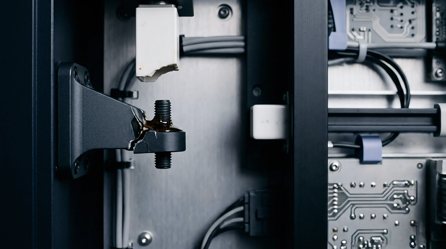
Geometric Deviation
Mechanical inconsistency in the adhesive layer between two mated surfaces defines the physical profile of an assembly. Achieving a uniform bondline thickness variance prevents the formation of hot spots in high power electronics. The measurement applies to the z-axis gap between a die and its substrate.
Beyond the specified limits, the adhesive no longer provides a reliable thermal path.
Thermal Impact
Resistance to heat flow increases when the adhesive layer thickens, while thin sections risk electrical shorting or mechanical failure. A high bondline thickness variance leads to uneven heat dissipation across the chip surface. Stress concentrations occur at the boundary of thick and thin regions.
These localized forces often initiate delamination.
Process Control
Automated dispensing systems and precision placement tools regulate the volume and pressure used during assembly. Controlling the bondline thickness variance requires constant monitoring of adhesive viscosity and substrate flatness. Any shift in the curing temperature alters the final thickness profile.
Metrological Verification
Acoustic microscopy or cross-sectional imaging confirms the internal geometry of the bond. Technicians use these tools to verify that the bondline thickness variance remains within the tolerance set by the design engineer. Calibrated sensors measure the gap in microns to ensure repeatability.
The verification happens after the curing process is complete. If the variance exceeds ten percent of the target thickness, the assembly faces rejection to avoid long term failure.