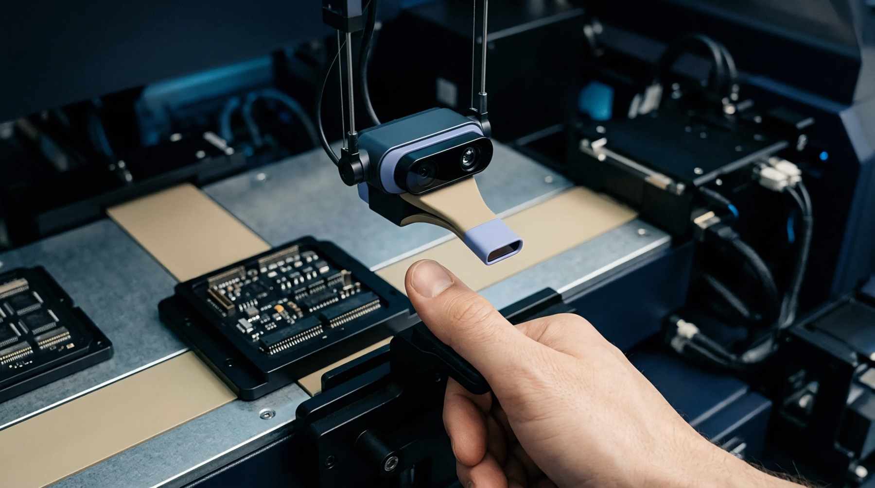
Physical Modification
Engineering adjustments change the conductive trace geometry or component placement on a populated substrate to address thermal or electromagnetic interference issues. Board layout redesign moves traces or shifts parts to satisfy signal integrity requirements identified during post-production testing. These mechanical shifts alter the current path and impedance characteristics of the high-speed logic lines.
Tolerance Verification
Calibration technicians measure the new signal arrival times against the baseline specifications defined by the original schematics. Verification confirms whether the trace path changes remain within the allowable margin of error for clock synchronization and noise floor stability. Instruments like vector network analyzers check the S-parameters of modified paths to ensure the new routing does not introduce unforeseen resonance at operating frequencies.
Performance Drift
Thermal expansion and solder joint mechanical stress create instability when physical configurations shift. Deviations from the intended signal path produce phase noise that exceeds the limits set by standard testing protocols. Maintaining constant proximity between bypass capacitors and power pins governs the effectiveness of the modification.
Manufacturing Constraint
Fabrication facilities enforce minimum spacing rules between copper features to prevent short circuits during the etching process. Designers ensure that every shift in geometry conforms to the specific density limits of the assembly line machinery. Adherence to these spacing rules ensures that the hardware performs reliably under the physical conditions specified by the component manufacturer.