Multi Sensor Thermal Gradient Modeling for Voltage Controlled Oscillators
Multi sensor thermal gradient modeling compensates transient substrate dynamics to hold RF voltage controlled oscillator frequency drift below 0.5 ppm.


Heat
A spatial temperature gradient of 1.2 degrees Celsius per millimeter across a Rogers RO4350B substrate shifts varactor junction capacitance by 14 femtofarads. This thermal shift pulls an 8 GHz voltage controlled oscillator center frequency by 4.2 MHz before ambient chamber sensors detect structural warming. Thermal energy propagates through printed circuit board copper layers, alumina substrates, and mold compounds at finite velocities governed by substrate thermal diffusivity.
High-frequency voltage controlled oscillators experience frequency instability due to non-uniform temperature profiles across active die junctions, varactor diodes, and passive inductance-capacitance resonant tanks.
Varactor diodes react sharply to localized thermal fluctuations. Junction capacitance changes with temperature as built-in potential shifts, yielding temperature coefficients between +200 ppm/°C and +800 ppm/°C depending on hyperabrupt junction doping profiles. High-Q tank inductors undergo physical expansion that increases inductance while substrate dielectric constants shift over temperature.
Heat flows along substrate copper traces. Active bipolar or CMOS transistors generate localized power dissipation that elevates local junction temperatures within milliseconds, while adjacent passive tank components warm over seconds through conductive substrate pathways.
| Substrate Material | Thermal Conductivity (W/m·K) | Dielectric Constant Drift (ppm/°C) | Coefficient of Thermal Expansion (ppm/°C) | Thermal Diffusivity (mm²/s) |
|---|---|---|---|---|
| FR-4 (Standard High-Tg) | 0.35 | +220 | 14.5 | 0.21 |
| Rogers RO4350B | 0.62 | +50 | 10.0 | 0.38 |
| Alumina (99.5% Al2O3) | 27.0 | +110 | 6.5 | 8.60 |
| Low Temperature Co-fired Ceramic | 3.30 | +60 | 5.8 | 1.25 |
Local power dissipation from adjacent power amplifiers or power management components creates dynamic microclimates across the board surface. Thermal propagation latency creates temporary temperature differentials up to 8.5 °C between sensor placement nodes and varactor nodes during transient power steps. Static temperature lookup tables fail under these conditions because the measured sensor node temperature does not match the instantaneous varactor junction temperature.
A 5 degrees Celsius transient differential across an RF varactor pair shifts center frequency by 180 parts per million before thermal equilibrium stabilizes.
Substrate choice determines thermal latency. Thin, high-conductivity substrates equilibrate rapidly, diminishing transient spatial gradients across small footprints. Thick multi-layer glass-epoxy laminates store heat, sustaining internal thermal gradients long after external thermal excitation ceases.
Failure to model thermal energy transfer across substrate copper layers results in phase-locked loop cycle slips and uncompensated frequency overshoot during RF power step transitions.

Topology
Sensor placement dictates spatial resolution and gradient reconstruction accuracy across RF assemblies. Deploying temperature sensors near high-power dissipators and sensitive passive tank structures captures orthogonal thermal vectors across the board surface. The physical layout of sensor arrays determines whether dynamic thermal transfer functions can resolve local junction temperature spikes before frequency drift exceeds phase-locked loop margin.
Transducer selection balances thermal response time, accuracy, and physical footprint. Surface-mount NTC thermistors in 0201 packages feature small thermal mass and fast time constants near 80 milliseconds, but display non-linear resistance-temperature characteristics that require polynomial linearization. Platinum resistance temperature detectors provide linear performance and absolute accuracy within 0.1 °C, yet their larger 0603 or 0805 footprints add thermal capacitance, introducing measurable lag.
Integrated digital sensors eliminate analog conditioning noise, but their sampling rates capped at 10 Hz to 100 Hz fail to track rapid thermal step transients occurring within microsecond windows. Integrated substrate bipolar junction diodes on MMIC die nodes deliver sub-millisecond response times, offering direct junction monitoring when coupled to high-speed analog-to-digital converters.
- Thermal Mass Mismatch ~ Placing heavy surface-mount thermistors next to low-mass bare die varactors creates phase lags in temperature tracking.
- Substrate Trace Conductive Coupling ~ Routing thick copper traces directly from power dissipator supply rails to sensor pads introduces localized thermal bias errors.
- Digital Bus Self Heating ~ Operating digital sensor interfaces at continuous high clock frequencies elevates internal silicon temperatures above local printed circuit board copper temperatures.
- Single Axis Sensor Placement ~ Aligning all thermal transducers along a single linear coordinate prevents detection of transverse thermal gradients across complex RF layouts.
Layout geometry demands symmetrical ground plane connections and dedicated thermal relief slots. Milled isolation cutouts in printed circuit boards divert conductive heat flux away from sensitive tank inductors, forcing thermal propagation along controlled pathways monitored by thermal sensor pairs. Thermal coupling capacitance between sensor pads and adjacent RF traces introduces parasitic loading, requiring grounded guard rings around high-impedance transducer lines.
Compliance with MIL-STD-883 Method 1012 requires thermal resistance verification across active die junctions to prevent unmodeled spatial temperature offset errors.
Latency limits real-time dynamic compensation. Sensor leads routed through inner board layers absorb heat from surrounding planes, causing sensor readings to lag actual surface copper temperatures. Placing temperature transducers along the direct heat flow path between major thermal sources and passive tank components maximizes differential sensitivity to dynamic temperature fronts.


Algorithm
Mathematical reconstruction converts discrete multi-point sensor outputs into localized temperature estimates at critical oscillator circuit nodes. Real-time digital signal processing translates raw transducer voltage readings into dynamic tuning voltage offsets. Polynomial models require sparse matrix solvers.
By continuously sampling an array of spatial temperature sensors, an embedded processor evaluates spatial gradient polynomials to compute varactor junction temperature and tank inductor temperature in real time.
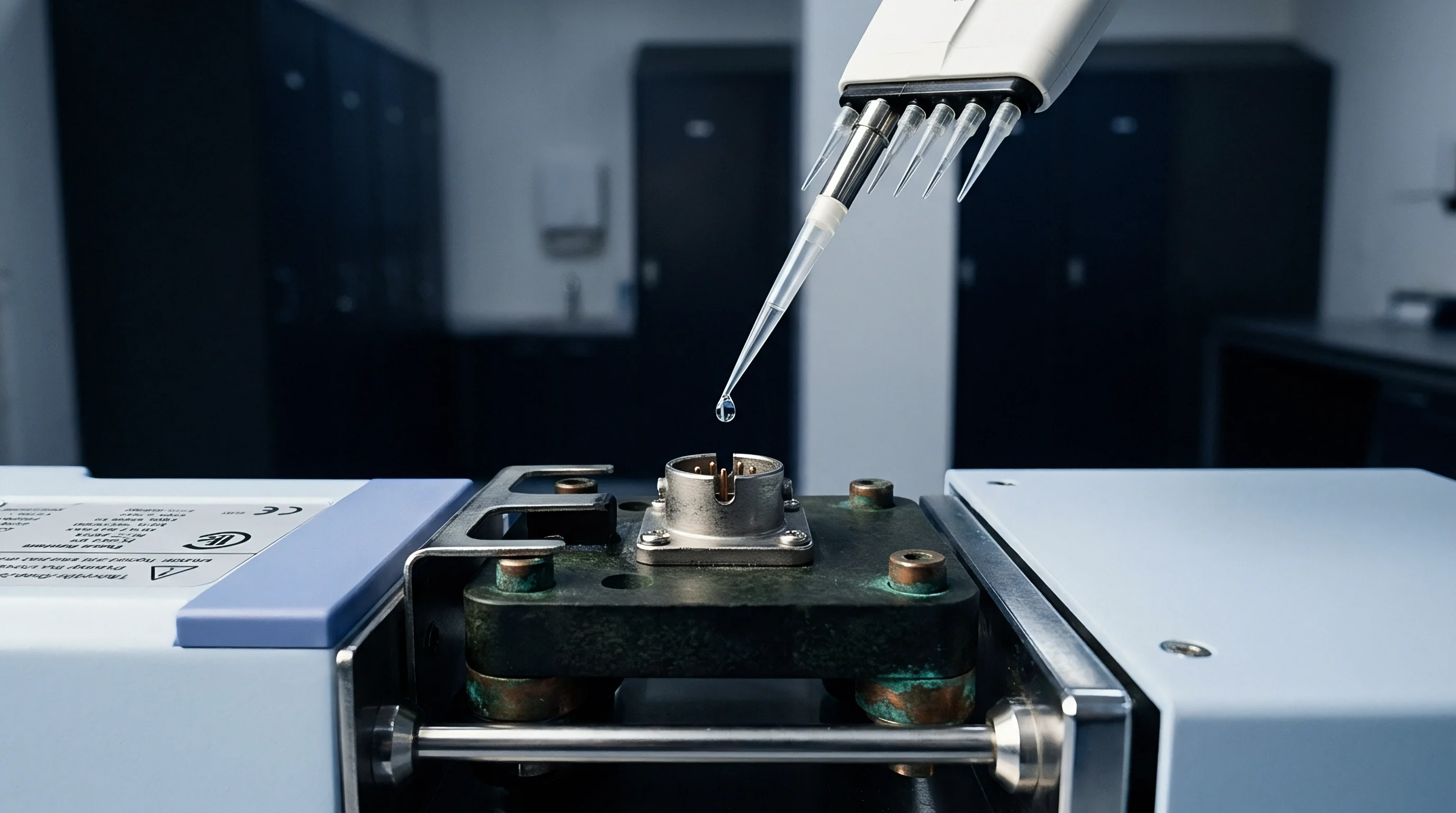
How Many Temperature Sensors Are Required for Sub-Ppm VCO Stability under Transient Thermal Gradients?
A two-dimensional spatial temperature field across an oscillator board surface maps to a second-order polynomial surface equation. Three non-collinear sensors establish the minimum baseline to compute first-order linear gradients in two orthogonal axes, along with absolute thermal offset. Adding a fourth sensor near the primary local heat source provides curvature modeling through second-order spatial partial derivatives.
Spatial thermal field reconstruction uses matrix multiplication to yield node temperatures from transducer array outputs.
Dynamic thermal modeling incorporates time derivatives of temperature to account for thermal diffusion latency. State-space thermal coupling matrices define internal heat transfer between discrete nodes. The state vector tracks node temperatures, driven by input thermal power vectors and constrained by thermal resistance and capacitance matrices.
Computing the time rate of change across sensor nodes predicts future temperature values at the varactor node, allowing feed-forward tuning voltage pre-distortion to counteract thermal frequency drift before physical heat reaches the junction.
Take a 10 GHz LC-tank voltage controlled oscillator fabricated on a 0.8 mm Rogers RO4003C substrate with three temperature sensors positioned around the resonator core. Assume a localized 3-Watt power step occurs 12 millimeters from the varactor node, generating a thermal front advancing across the substrate at 6.8 °C per second. A single-point thermal compensation table reading a sensor placed 5 millimeters from the varactor registers 28.2 °C when the varactor junction actually reaches 34.5 °C, leaving a 6.3 °C uncompensated differential.
This differential produces an 82 ppm frequency shift, equal to 820 kHz off center frequency, breaking carrier phase lock. Applying a multi-sensor three-node dynamic state-space matrix calculation reconstructs the varactor junction temperature within 0.15 °C throughout the 500-millisecond transient. The calculated pre-distortion voltage injected into the varactor tuning node suppresses residual drift to 0.35 ppm, holding the frequency shift within 3.5 kHz.
Incorporating first-order thermal rate of change terms into compensation equations eliminates dynamic hysteresis during rapid ambient temperature ramps.
Thermal hysteresis ruins static correction tables. Heating and cooling cycles generate differing stress-strain states within packaging materials, shifting component temperature coefficients based on thermal history. Matrix dynamic models track thermal rate direction, adjusting compensation gains dynamically when thermal gradients reverse direction.
The long-term stability of dynamic gradient matrices under localized mechanical stress relaxation across multi-layer substrate interfaces remains an open operational question.

Sweep
Empirical thermal chamber profiling extracts multi-sensor transfer function coefficients across operating temperature ranges. Chamber test time drives landed cost. Automated test benches apply controlled thermal ramps while recording oscillator center frequency, phase noise, and transducer voltages.
These calibration profiles populate multi-dimensional look-up tables or determine linear regression coefficients stored in non-volatile memory during factory calibration.
Test protocols evaluate both static thermal equilibrium and rapid transient states. Environmental chambers ramp ambient temperatures from -40 °C to +85 °C at controlled rates while spectrum analyzers log frequency drift. Peltier thermoelectric modules applied directly to substrate surfaces generate localized heat steps, simulating transient power dissipation from adjacent power amplifiers without altering ambient chamber temperature.
| Compensation Mode | Static Drift (-40 to 85 °C) | Transient Drift (20 °C/min) | Phase Noise Degradation @ 10 kHz Offset | PLL Lock Retention |
|---|---|---|---|---|
| Uncompensated Baseline | ±1450 ppm | ±3200 ppm | 12 dB | Lost |
| Single-Point Static Table | ±12 ppm | ±185 ppm | 8 dB | Cycle Slips |
| Two-Sensor Linear Gradient | ±2.5 ppm | ±14 ppm | 2 dB | Maintained |
| Four-Sensor Dynamic Matrix | ±0.4 ppm | ±0.8 ppm | 0.3 dB | Maintained |
| Data recorded at 10 GHz carrier frequency on 0.8 mm Rogers RO4003C evaluation boards inside controlled thermal chambers. | ||||
- Equilibrium Baseline Mapping ~ Measure open-loop oscillator frequency across static temperature steps to baseline intrinsic component temperature coefficients.
- Localized Transient Heating ~ Apply controlled power pulses to adjacent substrate heaters while logging multi-sensor array time responses.
- Matrix Coefficient Extraction ~ Solve linear systems of equations to calculate spatial conduction coefficients between sensor nodes and passive tank nodes.
- Dynamic Compensation Calibration ~ Inject calculated voltage offsets into the varactor tuning node during temperature ramps to verify loop stability.
- Phase Noise Verification ~ Record phase noise profiles at maximum thermal ramp rates to ensure digital pre-distortion processing adds no spurious spectrum components.
Phase noise monitoring during thermal sweeps reveals dynamic stability degradation. Thermal transients generate localized mechanical stresses across surface-mount solder joints, inducing low-frequency flicker noise modulation onto the varactor junction. Fast Fourier Transform analysis of frequency drift residuals isolates unmodeled spatial thermal time constants from intrinsic phase noise floors.
Thermal transients degrade oscillator phase noise close to the carrier by introducing low-frequency noise modulation across varactor junction capacitances.
Unmodeled physical strain across component packaging introduces non-repeatable frequency offsets during rapid temperature sweeps. Transient frequency instability often stems from unmodeled varactor packaging stress rather than spatial thermal gradient delays across substrate copper layers.

Logistics
Transducer selection fixes the bill of materials cost, calibration overhead, and long-term manufacturing yield. Sourcing thermal sensors for high-reliability RF assemblies demands evaluation of component tolerances, long-term drift rates, and second-source packaging compatibility across production batches.
| Transducer Technology | Initial Accuracy | Thermal Response Time | Unit Price (10k volume) | Primary Sourcing Risk |
|---|---|---|---|---|
| NTC Thermistor (0201) | ±0.5% | 80 ms | $0.04 | Beta value tolerance variations between lot batches |
| Thin Film PT100 RTD | ±0.15 °C | 350 ms | $0.85 | Sole-source packaging dependencies |
| Digital I2C Sensor IC | ±0.10 °C | 1200 ms | $0.65 | Silicon fabrication allocation shifts |
| Substrate BJT Sense Diode | ±1.0 °C | 0.5 ms | $0.00 (On-Die) | Wafer process variation across foundry runs |
Calibration overhead dominates module landed cost. Single-point static calibration requires 45 seconds per board in automated test fixtures, whereas multi-sensor transient matrix extraction extends test duration to 3.5 minutes per unit. High-volume manufacturing requires balancing sensor array count against the capacity ceiling of environmental test chambers.
- Review component datasheets to verify maximum thermal drift specifications over 2000 hours of continuous operation at rated temperatures.
- Inspect vendor qualification packages for compliance with AEC-Q100 or AEC-Q200 stress test requirements.
- Audit second-source wafer fabrication facilities to ensure uniform temperature coefficient parameters across component production batches.
- Standardize sensor package footprints across the printed circuit board assembly to enable alternate vendor substitutions during supply disruptions.
Component tolerance accumulation alters linear regression matrix outputs. Thermistor resistance drift exceeding 1% over field service lifespans introduces static offset errors into thermal gradient calculation engines, degrading dynamic frequency compensation performance. System specifications must account for sensor aging trajectories to maintain phase noise and frequency tolerance margins over ten-year operating lifespans.
Standard purchasing contracts specifying AEC-Q200 Grade 1 passive components restrict allowable resistance drift to 1 percent after thermal shock testing, enforcing recalibration intervals across long field service lifespans.