Multi Frequency Phase Sensitive Eddy Current Sensing Circuits for Sub Skin Depth Target Calibrations
Decouple thickness from liftoff in sub-skin-depth targets by inverting multi-frequency quadrature demodulation matrices mapped to certified metallic shims.


Vector
Driven by alternating current, planar spiral coils induce secondary magnetic fields within conducting targets, producing complex impedance paths that reflect conductivity, permeability, liftoff, and plate thickness. Once target thickness drops below standard electromagnetic skin depth, the reflected magnetic field no longer decays exponentially through the metal. Flux crosses the far boundary instead, shifting coil impedance from a classical diffusion spiral into a boundary-limited path set by sheet conductance.
Conventional single-frequency gear flattens this trajectory into an unresolved scalar voltage, leaving thickness changes indistinguishable from probe liftoff.
Isolating geometric liftoff from sub-skin thickness shifts requires phase-sensitive quadrature demodulation across several excitation frequencies at once. These range from tens of kilohertz up to twenty megahertz to suit the boundary conditions of sub-millimeter metal foils, thin-film metallizations, and structural sheet alloys. Coil impedance divides cleanly: the real component tracks resistive dissipation from target eddy currents, while the imaginary component registers inductive energy stored in the liftoff gap and target permeability.
At twenty megahertz over thirty-micron copper foil, phase sensitivity yields forty-eight millivolts of quadrature displacement per micrometer of thinning under continuous five-hundred-milliampere bridge excitation.
When conductor thickness falls well under three skin depths, the phase angle of the reflected impedance vector decouples from diffusion lag. The phase response then runs linearly with sheet conductance ~ the product of electrical conductivity and physical thickness. Because liftoff shifts trace an orthogonal path on the complex impedance plane at high frequencies, dual- or triple-frequency phase detection yields the algebraic footing needed to separate liftoff from the thickness matrix.
Probe design sets the initial noise boundary. Differential layouts suppress common-mode thermal drift and ambient interference, feeding microvolt-level imbalance signals directly into low-noise preamplifiers. Single-ended absolute coils give better raw sensitivity across broad thinning areas, though they require high-order DC-coupled temperature tracking at the front end to keep thermal baseline wander from masquerading as metal loss.
Coil dimensions govern inspection footprint. Narrow outer diameters isolate localized thinning, whereas broader coils cast the uniform flux profiles needed for sheet conductance runs. Because higher excitation frequencies drive up inductive reactance, resonant tuning must be kept tight to protect preamplifier dynamic range.
Phase angle separation collapses when the excitation frequency drops into the resistive limit.
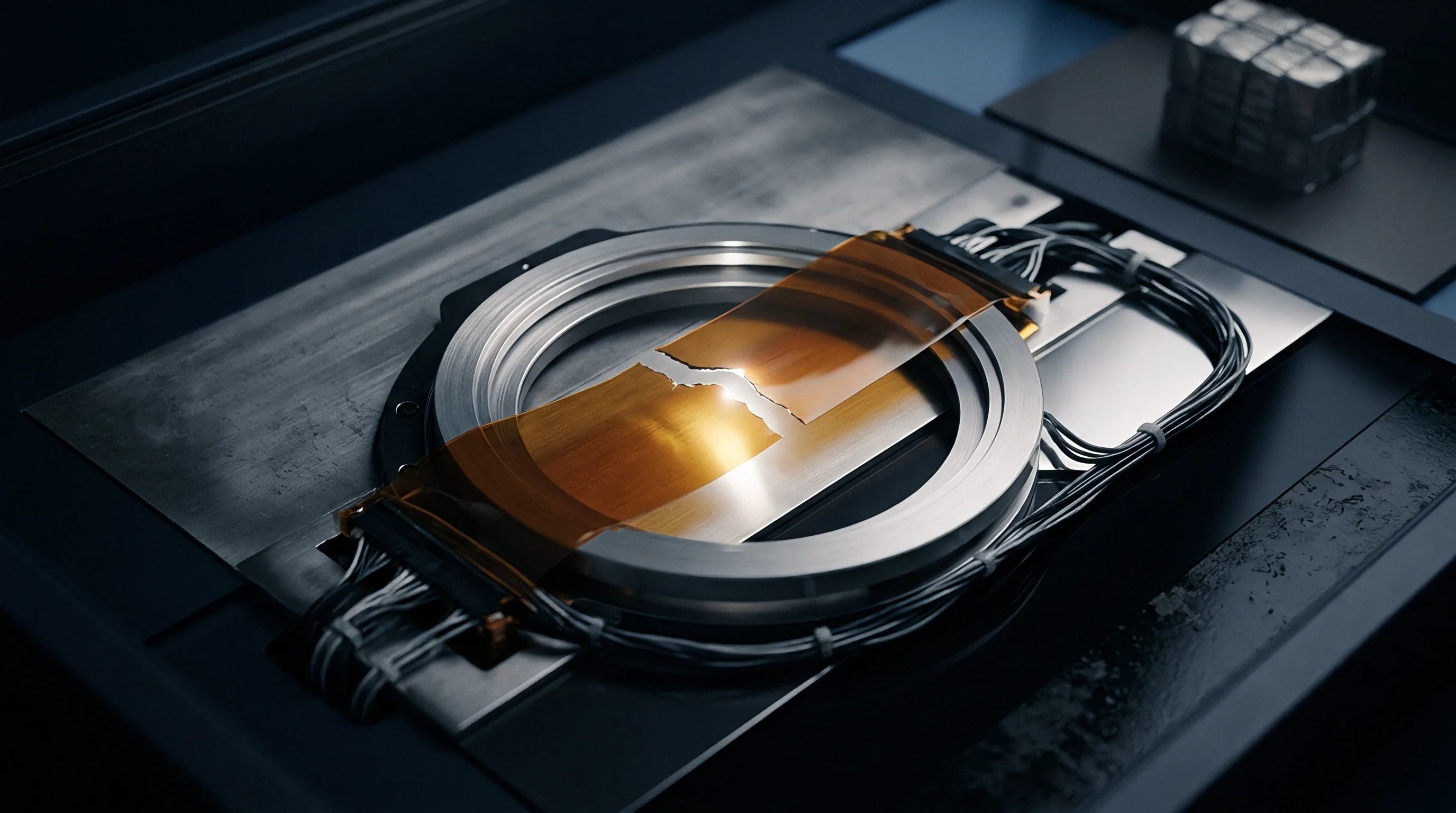
Demodulation
Direct digital synthesis generators produce concurrent excitation frequencies, sending composite waveforms through balanced, high-linearity drivers to the probe. Bridge or differential sensor output then routes to a low-noise analog chain with sub-nanovolt input voltage noise density. Analog multipliers, direct-conversion switching mixers, or high-speed pipeline ADCs subsequently break the multi-tone RF signal into baseband in-phase and quadrature components.
Multi-frequency analog demodulation remains vulnerable to channel-to-channel phase skew. At five megahertz, an uncorrected phase delay of one-tenth of an electrical degree produces an apparent thickness error above two percent on thin austenitic stainless steel. Synchronous quadrature demodulators counter this with matched analog switches clocked by non-overlapping divide-by-four signals from a master crystal, maintaining orthogonality across sixty decibels of input dynamic range.
| Demodulation Scheme | Sampling Rate | Dynamic Range | Phase Noise at 1 MHz | Settling Window |
|---|---|---|---|---|
| Dual Balanced Switching Mixer | Analog Baseband | 84 dB | -112 dBc/Hz | 12 microseconds |
| Direct RF Under-Sampling ADC | 125 MSPS | 76 dB | -128 dBc/Hz | 3.5 microseconds |
| Baseband Synchronous Sampling | 10 MSPS | 92 dB | -134 dBc/Hz | 28 microseconds |
| Digital Down-Converter FPGA | 250 MSPS | 88 dB | -140 dBc/Hz | 1.8 microseconds |
Digital down-conversion designs generate local oscillators directly inside an FPGA. Fast digitizers sample the composite bridge signal ahead of any mixer stages, sending raw data through cascaded integrator-comb decimation stages and FIR shaping filters. This digital separation extracts each tone with complete isolation, avoiding the carrier feedthrough and 1/f noise inherent to analog mixers.
Accurate calibration requires tight phase alignment between excitation references and demodulation clocks. Trace lengths, amplifier group delays, and probe cable capacitance all introduce frequency-dependent phase rotation. Digital offset tables, built during an initial air-reference run, correct these shifts by bringing the baseline back to the origin of the impedance plane.
Cable capacitance shifts the resonance of high-frequency sensing heads. Shielded triaxial lines curb stray coupling, which otherwise distorts the input impedance matrix across broad frequency steps.
Differential target calibrations cancel residual carrier feedthrough, compensating for lower mixer baseband isolation.

Shim
Certified reference foils and precision gauge blocks anchor the conversion of raw voltage coordinates into physical dimensions. For sub-skin-depth targets, calibrating eddy current instruments requires step wedges cut from the same metallurgical heat to guarantee matched conductivity and permeability. A conductivity offset of two percent between reference and production stock throws off sub-skin calculations, skewing thickness readings by dozens of micrometers.
Standard routines layer precision shims over non-conductive ceramic blocks to replicate isolated thickness steps. Non-conductive polyimide shims beneath the probe establish known liftoff increments, allowing the system to map liftoff behavior across the full working clearance. Running at two separate frequencies separates the response into two distinct vectors: the lower frequency tracks liftoff independent of boundary effects, while the higher frequency captures coupled liftoff and sheet conductance.
ASTM E2338 specifies reference standard validation criteria that disqualify calibration specimens exhibiting surface micro-roughness variations greater than five percent of minimum inspection depth.
Sub-skin thickness inversion relies on a dual-frequency algebraic projection. In an inspection of sixty-micron rolled aluminum foil with a conductivity of thirty-four megasiemens per meter, testing at two megahertz gives an electromagnetic skin depth of roughly sixty-one micrometers, placing the workpiece right in the sub-skin transition region. Testing simultaneously at ten megahertz yields a skin depth of twenty-seven micrometers, saturating the top-surface response and isolating the liftoff component.
The signal chain yields raw demodulated voltages for both frequencies, formatted as in-phase and quadrature pairs. A transformation matrix separates the terms:
Voltage real component at low frequency: V1R = K11 multiplied by liftoff plus K12 multiplied by sheet thickness.
Voltage imaginary component at low frequency: V1I = K21 multiplied by liftoff plus K22 multiplied by sheet thickness.
Voltage real component at high frequency: V2R = K31 multiplied by liftoff plus K32 multiplied by sheet thickness.
Voltage imaginary component at high frequency: V2I = K41 multiplied by liftoff plus K42 multiplied by sheet thickness.
The K coefficients come from measurements taken across four known conditions: zero liftoff at base thickness, a calibrated liftoff step at base thickness, zero liftoff at reduced shim thickness, and a calibrated liftoff step at reduced shim thickness. Inverting this four-by-two matrix decouples mechanical gap shifts from genuine metal thinning with sub-micron repeatability.
- Reference standard conductivity drift introduces baseline scaling offsets when thermal stabilization remains incomplete during bench runs.
- Galvanic oxide formation generates superficial resistive layers that alter high-frequency capacitive displacement current return paths.
- Liftoff angle tilt warps the magnetic coupling coefficient, introducing non-linear quadrature components that distort thin-foil matrix projections.
- Substrate magnetic backing reconfigures return flux lines, requiring dedicated calibration matrices when ferromagnetic backers support non-ferrous foils.
Multi-layered calibration targets require explicit handling of interface contact resistance. Microscopic air gaps between stacked shims disrupt eddy current circulation, yielding a lower apparent conductivity than a solid sheet of the same total gauge. Reference foils produced by chemical milling match the actual metallurgical structure of monolithic stock far more reliably.
Section 8 of ISO 15549 invalidates instrument calibration certificates when reference foil alloy chemistry deviates from the production workpiece batch by more than half a percent.
Topology
Front-end analog topology fixes signal quality before inversion algorithms ever run. Transformer-coupled bridges isolate high-power drive noise from preamplifier inputs, cutting out the ground loops common in automated factory equipment. Constant-current absolute probes preserve phase integrity over long cables, though differential bridge circuits provide better baseline rejection against ambient temperature shifts.
Differential bridge setups place two matching coils directly over the work area. One coil monitors the production foil while the other balances against an internal reference shim kept at the same temperature. This symmetry knocks down thermal impedance drift by thirty-four decibels, allowing preamplifiers to run at twenty times the gain without overdriving their output stages.
Thermal drift cancels when twin inductive elements track identical mechanical orientations across shared mounting blocks.
Tuning for resonance brings real compromises. Placing sensing coils in parallel resonance with polyphenylene sulfide capacitors boosts target impedance signals and improves signal-to-noise ratios. But resonance restricts usable circuit bandwidth, creating phase distortion when multi-frequency tones span wide frequency decades.
Broadband untuned circuits maintain flat group delay and keep phase orthogonality intact across all tones, though at the expense of a higher noise floor.
Grounding configuration decides whether microvolt phase signals survive plant-floor electrical noise. Double-shielded braided cable works best when the outer braid grounds to the chassis and the inner braid ties to analog ground strictly at the instrument faceplate. Leaving the probe shell floating prevents stray currents from routing through the machine frame.
| Topology Family | Gain Bandwidth | Common Mode Rejection | Phase Drift Coefficient | Implementation Cost |
|---|---|---|---|---|
| Transformer Isolated Bridge | 25 MHz | 96 dB | 0.012 deg per degree C | High |
| Active Transimpedance Drive | 50 MHz | 72 dB | 0.045 deg per degree C | Moderate |
| Differential Resonant Tank | 12 MHz | 88 dB | 0.085 deg per degree C | Low |
| Current-Driven Low-Z Node | 100 MHz | 68 dB | 0.018 deg per degree C | High |
Power distribution calls for separate low-dropout regulators on each generator and demodulator rail. Switching spikes from primary converters bleed easily into the analog section, producing phase artifacts that undermine the inversion math. Series ferrite beads on analog supply pins must sustain high impedance across the entire multi-frequency excitation spectrum.
Omitting thermal compensation on driver stage series resistors converts ambient factory temperature swings into fictitious target thinning reports, destroying process capability metrics.
Audit
Sourcing multi-frequency front ends reveals uneven capability across suppliers. Most commercial instruments are built for heavy structural inspection, relying on large coils and drive stages capped below two megahertz. These systems fall flat on sub-hundred-micron work.
Sourcing for sub-skin-depth measurements requires verifying RF front-end linearity, phase stability, and the capacity to wind custom miniature probes.
Procurement balances turnkey packages against custom board designs. Packaged systems include certified enclosures and complete calibration tools, but they tie operations to proprietary probes with lead times often topping twenty weeks. Modular, board-level front ends on open PXIe or industrial Ethernet standards make second-sourcing straightforward and protect production uptime.
Parts availability actively steers receiver design. Low-noise differential amplifiers and fast analog multipliers hit frequent supply allocations. Building around modular daughtercards allows swapping out baseband switching mixers for fast digitizers without having to rework the main processing backplane.
Bills of materials must also be vetted for the lifecycle status of high-frequency baluns and RF clock distribution chips.
- Validate analog channel phase tracking over operational temperature swings from ten to fifty degrees Celsius.
- Confirm low-noise preamplifier input impedance stability across the entire active multi-frequency excitation span.
- Audit probe coil winding consistency across replacement batches using precision LCR meters at excitation frequencies.
- Inspect supplier calibration coupon dossiers to ensure alloy composition matches production workpiece specifications.
Second-source validation relies on testing against identical alloy foils. A variance of just five turns on a miniature ferrite core shifts baseline inductance by eight percent. That divergence moves the probe resonance and corrupts the matrix inversion coefficients, meaning system firmware must include automated coil balancing.
Traceability records must verify thickness via contact interferometry or mechanical profilometry prior to eddy current calibration. Relying on nominal sheet thicknesses from mill purchase orders invites systematic measurement error. Quality audits require suppliers to verify dimensional standards directly rather than relying on unconfirmed conductivity values.
The open challenge rests on whether automated factory recalibration routines can dynamically compensate for high-temperature metallurgical phase transitions in ultra-thin alloy targets without interrupting continuous process lines.