Dynamic Thermal Transient Effects on Transducer Phase Margin in Closed Loop Hydraulic Flight Controls
Dynamic thermal transients alter transducer winding impedance and demodulator filter delay, eroding closed-loop hydraulic actuator phase margin.
Shock
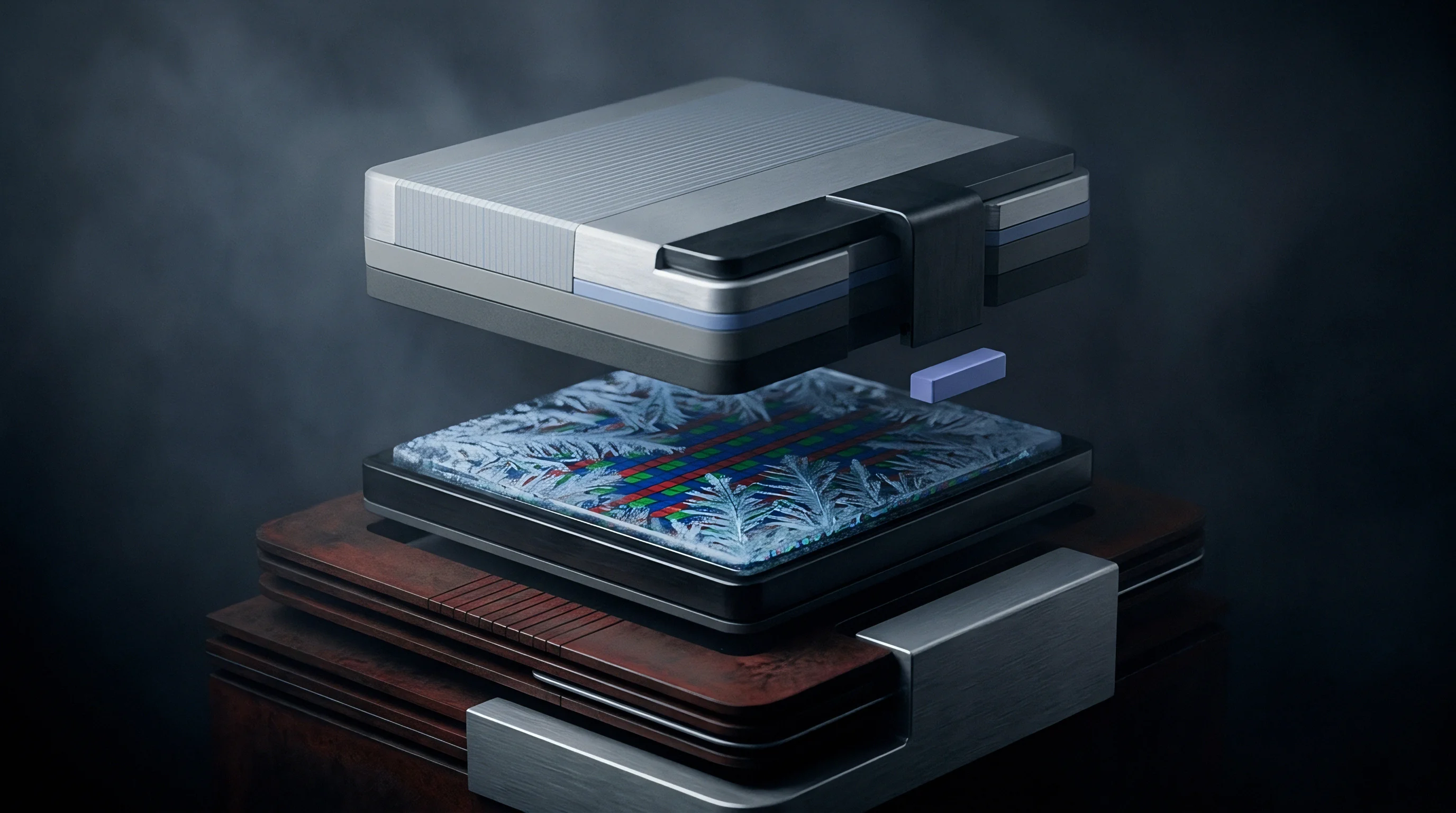
At high cruise altitudes, hydraulic fluid resting in an unheated wing bay chills down to -40°C. When primary flight surfaces suddenly deploy, the main system pumps drive oil at +105°C straight through the line, sending a sharp thermal wavefront into the linear variable differential transformer housed in the electrohydraulic servovalve body. Actuator response during this transient hinges entirely on position transducer stability.
Localized heat streams make the surrounding metal expand at uneven rates. The sensor’s outer sleeve warms up seconds before conduction reaches the inner core or primary windings, and that differential expansion displaces the mechanical null by several micrometers while core magnetic permeability shifts and coil resistance climbs.
A temperature rate of change exceeding eight degrees Celsius per second across an unshielded transducer sleeve induces twelve micrometers of mechanical null offset at three thousand pounds per square inch supply pressure.
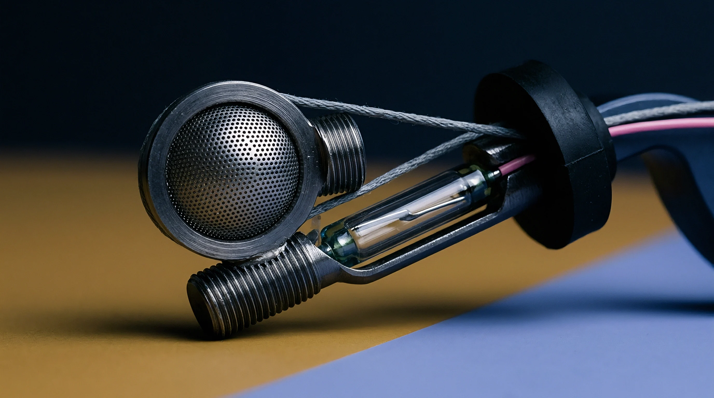
Alternating magnetic fields generated by the primary windings link to the secondary coils through the movable ferromagnetic core. As heat spreads through the unit, copper resistivity climbs at roughly 0.393 percent per degree Celsius, shifting primary coil impedance between resistance and inductive reactance and throwing the primary excitation current out of phase with the drive voltage while fluid viscosity drops fivefold.
Thermal Fluid Inrush across Primary Actuators
Hot oil striking one side of the housing sets up steep radial and axial thermal gradients. Mechanical clearances between the spool extension rod and sensor liner expand or contract unevenly. At the same time, high-pressure boundary layers accelerate convective heat transfer from the phosphate ester fluid into the nickel-iron magnetic shielding, changing air-gap geometry along the sensing stroke as the core expands.
- Asymmetric sleeve distortion bends the internal bore axis and shifts mechanical null calibration by up to fifteen micrometers.
- Permeability gradient generation creates non-uniform flux paths across secondary pick-up coils during rapid heating cycles.
- Potting compound thermal expansion imposes mechanical stress against winding layers, triggering localized microphonic voltage spikes and transient distortion.
- Connector pin thermoelectric offsets generate parasitic DC bias voltages that distort carrier demodulation zero-crossing detectors.
Raw brass housings warp unevenly under these conditions. If the housing walls expand faster than the internal bobbins, winding compression loosens or binds, altering self-inductance and shifting the electrical carrier angle. Closed-loop flight computers read that phase lag as delayed spool travel, commanding erroneous trim currents through the servovalve coils.
Winding Resistivity Slopes and Permeability Shifts
Sudden heating alters the magnetic behavior of the high-permeability nickel-iron alloys in the core. Below magnetic saturation, core permeability shows a non-linear temperature coefficient, rising initially before dropping off sharply near the Curie point. In typical flight-control LVDTs, primary inductance drifts by several millihenries within two seconds of fluid contact.
Copper resistance follows a predictable slope, directly dictating current phase lag relative to the flight control computer excitation carrier. When resistance climbs from eighty ohms at sub-zero temperatures to one hundred twenty ohms under hot hydraulic flow, the phase displacement between driving voltage and primary magnetic flux widens by eight to fifteen degrees, corrupting spool position feedback.
Internal ratiometric coil wiring cancels uniform thermal expansion across the operating envelope, but cannot balance localized, transient temperature gradients.
Coupling
Flight control computer carrier excitation typically runs between 2.5 kHz and 10 kHz. Demodulation hardware has to pull position data from the secondary amplitude modulation without introducing extraneous phase delay into the actuator inner loop. When thermal stress alters transducer impedance, secondary voltages develop a carrier phase lead or lag relative to the excitation reference.
Synchronous demodulators multiply the incoming secondary differential signal against that reference carrier. If a thermal gradient introduces a twelve-degree phase shift between the secondary return and the demodulation reference, baseband output amplitude drops in proportion to the cosine of the mismatch, producing uncompensated scale errors and residual carrier ripple while demodulator tracking loops add group delay.
Phase alignment between carrier excitation and secondary pick-up signals governs baseband loop gain stability regardless of core position.
Analog low-pass filters downstream of the demodulator strip away high-frequency excitation ripple, but their intrinsic group delay eats into control loop phase margin at actuator crossover. On flight computer analog front-end boards, warming filter capacitors and shifting operational amplifier open-loop gain alter filter cutoff frequencies, worsening inner loop delay.
Does Rapid Fluid Inrush Degrade Servovalve Phase?
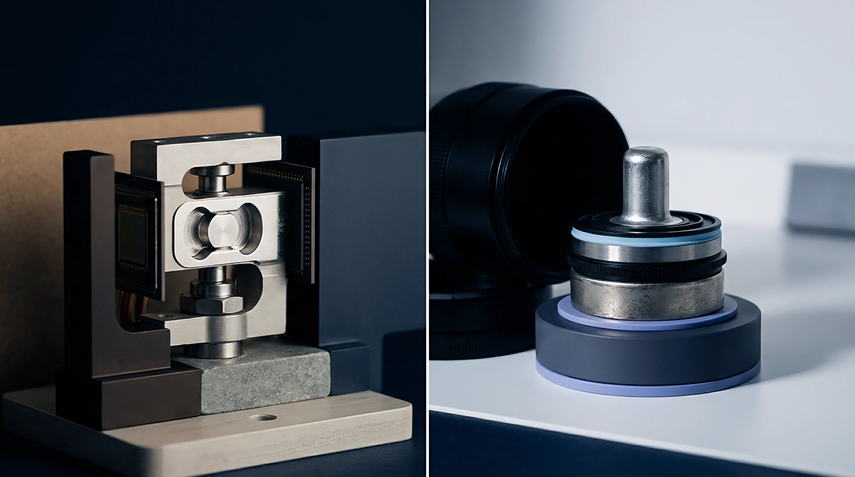
Electrohydraulic actuators rely on rapid spool displacement feedback to stabilize high hydraulic flow amplification. When sudden maneuvers dump hot fluid into the valve body, non-uniform heating of the sensor coils alters demodulated position feedback slope within milliseconds, distorting the velocity feedback calculated by digital differentiation.
Actuator damping suffers immediately. If the position feedback loop develops phase lag near the hydraulic fluid resonance frequency, the actuator piston can settle into sustained, low-amplitude limit cycle oscillation. This surface buzz causes premature structural fatigue and forces hydraulic pumps to work harder while analog filters drift with ambient temperature.
| Stage Element | Cold Phase Lag at 10 Hz | Hot Phase Lag at 10 Hz | Transient Phase Shift | Dominant Mechanism |
|---|---|---|---|---|
| Primary Winding Circuit | 1.2 deg | 4.8 deg | +3.6 deg | Copper resistance increase and inductance drift |
| Magnetic Core Flux Path | 0.8 deg | 2.1 deg | +1.3 deg | Eddy current damping and permeability variation |
| Synchronous Demodulator | 0.0 deg | 3.5 deg | +3.5 deg | Reference carrier mismatch attenuation phase lag |
| Four-Pole Ripple Filter | 14.2 deg | 19.6 deg | +5.4 deg | RC component drift lowering filter corner frequency |
| Analog-to-Digital Converter | 2.4 deg | 2.4 deg | 0.0 deg | Fixed group delay from oversampling pipeline |
Demodulator Synchronization Error across Carrier Waves
Digital signal processors often run software phase-locked loops to track carrier shifts caused by harness capacitance and coil temperature swings. In steady-state operation, these routines hold near-zero phase error between the reference and sensor return signals, but steep thermal ramps push the tracking bandwidth past its limits.
When inrushing fluid drives heating rates of ten degrees per second, coil impedance changes faster than narrow-band tracking filters can follow while preserving noise rejection. The resulting tracking lag generates a temporary error of several degrees, attenuating demodulated position amplitude and injecting low-frequency phase distortion directly into the flight control loop.
Transducer carrier excitation tracking loops maintain stable loop phase only when carrier phase tracking bandwidth exceeds the maximum thermal rate of change by two orders of magnitude.

Erosion
Flight control surface actuation systems require robust stability boundaries across the entire flight envelope. Military and commercial aviation standards enforce minimum margins of 45 degrees of phase and 6 decibels of gain in closed loops. Thermal transients erode these safety buffers silently, with no warning flags on cockpit displays.
Actuator inner position loop crossovers generally sit between 8 Hz and 20 Hz to decouple from structural aeroelastic modes while preserving command tracking. Any phase lag from coil resistance changes, demodulator tracking slips, and filter corner migration adds directly into loop phase at that crossover frequency, dropping phase margin below thirty degrees.
45.0 degrees of open-loop phase margin at 12 Hz crossover degrades to 28.4 degrees during a ninety-degree fluid inrush transient.
Take an actuator operating with an open-loop crossover at 12 Hz: at room temperature, the servovalve and cylinder provide 52 degrees of phase margin. When a high-rate maneuver brings hot fluid into the chilled housing and raises coil temperature by 80°C in three seconds, stability across the loop deteriorates in steps.
- Primary coil impedance shifts as copper temperature rises, introducing 4.1 degrees of electrical phase lag into the primary magnetic excitation field.
- Core flux link delay increases by 1.6 degrees due to elevated eddy currents and changing permeability in the magnetic sleeve alloy.
- Phase-locked demodulation tracking slips behind the carrier shift, adding 3.2 degrees of phase delay at the baseband demodulator output.
- Analog ripple filter components warm up inside the local manifold electronics box, dropping the 120 Hz filter corner to 92 Hz and introducing 5.8 degrees of extra group delay at 12 Hz.
- Cumulative inner-loop phase lag totals 14.7 degrees, directly subtracting from actuator phase margin and eroding stability to 37.3 degrees.
With actuator compliance softening effective hydraulic stiffness, loop phase margins falling below 30 degrees let servovalve spool overshoot amplify aerodynamic buffeting loads on mechanical linkages. Control surface flutter can couple into wing torsional modes, threatening airframe structure before thermal equilibrium restores baseline damping.
| Transient Elapsed Time | Fluid Temperature | Sensor Coil Temperature | Loop Phase Margin at 12 Hz | Loop Gain Margin |
|---|---|---|---|---|
| 0.0 s (Cold Soak) | -40°C | -38°C | 53.2 deg | 8.4 dB |
| 1.5 s (Initial Inrush) | +85°C | -10°C | 46.1 deg | 7.2 dB |
| 3.0 s (Peak Gradient) | +105°C | +42°C | 35.4 deg | 5.8 dB |
| 6.0 s (Secondary Soak) | +105°C | +88°C | 38.9 deg | 6.1 dB |
| 15.0 s (Equilibrium) | +105°C | +102°C | 44.7 deg | 6.9 dB |
| Values measured at 3000 psi supply pressure using MIL-PRF-83282 hydraulic fluid at 12 Hz crossover frequency. | ||||
Crossover Frequency Stability and Margin Loss
Gain crossover frequency determines actuator command responsiveness and disturbance rejection capability. Pushing crossover higher leaves less room for phase lag across sensor channels; if signal-conditioning circuits introduce thermal phase delay, crossover frequency drops with falling amplitude, or loop instability crops up if gain peaks near resonance.
As low-pass filter corners drift downward, the interaction between cylinder fluid resonance and electrical filter phase delay produces resonant peaking. If loop phase slips past -180 degrees while open-loop gain stays above unity, limit-cycle oscillations and rod chatter set in immediately until flight software aborts automatic trimming.

Step Transient Response across Temperature Extremes
Flight control actuators responding to pilot commands under thermal shock show pronounced overshoot and sluggish settling. During cold-to-hot hydraulic switching in flight test regimes, commanded step inputs reveal severe damping loss; systems tuned for a 0.707 damping ratio at room temperature often drop to 0.35 during peak thermal transients.
Actuator load-holding stiffness degrades when feedback lags rod movement, allowing surface limit cycles to form. When aerodynamic loads fluctuate, the actuator yields slightly before the servovalve spool displaces to correct it, degrading control precision during high-speed, low-altitude runs.
Failure to accommodate thermal phase erosion leads to flight envelope restrictions and catastrophic mechanical fatigue across flight control surface hinges.

Filter
Conditioning electronics convert raw differential transformer outputs into digital values used by control algorithms. Analog filters strip out high-frequency carrier ripple and prevent aliasing at the ADC input, but every analog stage introduces phase lag that scales inversely with cutoff frequency and drifts directly with passive component values under heat.
Passive filter topologies depend on surface-mount capacitors and metal film resistors whose values drift over the operating temperature range. Ceramic capacitors with X7R dielectrics lose capacitance as temperatures approach +125°C, pushing filter cutoffs upward. COG and NPO dielectrics stay stable across temperature, but their lower volumetric efficiency limits allowable capacitance in cramped avionics enclosures.
A standard clause in DO-160G Section 5 imposes thermal rate qualification testing up to ten degrees Celsius per minute across electronic sub-assemblies.
Digital alternatives replace analog demodulation filters with oversampled converters and FIR software filtering, providing deterministic linear phase across wide temperature swings. However, they incur fixed processing latencies that consume part of the loop phase budget regardless of ambient thermal conditions.
Will Demodulation Filtering Induce Unmodeled Flight Instability?
Actuator control design involves balancing carrier ripple suppression against inner-loop phase margin. High-order Bessel or Butterworth filters eliminate 5 kHz carrier harmonics and prevent ripple currents from heating servovalve motor coils, but their steep phase roll-off cuts deeply into stability margins near 15 Hz.
When localized manifold heat drifts analog ripple filter components by eight percent, filter group delay at 12 Hz grows by 4.2 milliseconds. In an actuator operating at 15 Hz crossover, every additional millisecond of signal delay subtracts 5.4 degrees of phase margin directly from the control loop.
- Analog synchronous demodulation achieves minimal baseline group delay but exhibits significant phase drift under component temperature changes.
- Oversampled sigma-delta conversion eliminates passive component temperature drift but introduces fixed digital filter group delays exceeding two milliseconds.
- Direct carrier-sampling analog-to-digital converters eliminate low-pass demodulation filters entirely, shifting phase-tracking burdens to processor firmware.
- Dual-frequency carrier excitation schemes compensate for temperature-induced primary inductance variations through simultaneous multi-frequency impedance calculation.
Tracking Algorithms and Phase Compensation Topologies
Modern flight control computers use adaptive phase compensation to counter thermal phase shifts dynamically. Quadrature demodulation extracts both the in-phase and quadrature components of the secondary signal to calculate true displacement amplitude independent of carrier phase offsets, preventing amplitude loss caused by phase misalignment.
Quadrature extraction demands considerable computation, adding fixed processing latency to digital execution frames while components face thermal shock screening. In systems running at 1 kHz, frame calculation delay adds 3.6 degrees of phase lag at 10 Hz, eroding much of the phase margin gained by dropping analog filter stages.
Whether closed-loop phase adaptation algorithms can track multi-axis thermal shock waveforms without injecting sub-harmonic phase noise into hydraulic control loops remains an open technical challenge.

Proof
Verifying transducer stability under rapid hydraulic heating demands test rigs that deliver synchronized thermal and fluid pressure shocks. Standard environmental chambers running static air profiles cannot recreate the steep internal gradients produced by pressurized oil flowing through an aircraft manifold. Rig hardware must cycle fluid from -54°C to +135°C within five seconds at 4000 psi.
Instrumentation arrays capture carrier phase angle, demodulated DC output, servovalve spool position, and actuator ram position simultaneously across fluid transients. High-speed acquisition channels sample primary current and secondary voltages at 1 MHz to isolate phase shifts within individual carrier cycles, even as component lead times stretch past fifty weeks.
Test data taken during rapid fluid switching reveals eight degrees of uncompensated carrier phase shift within the first 1.8 seconds of oil inrush.
Procurement specifications for primary flight actuator position sensors must define dynamic phase drift limits directly in RFPs. Standard vendor datasheets routinely quote static accuracy under thermal soak, glossing over phase lag under high thermal slew rates. Omission of transient phase specs regularly forces costly hardware redesigns late in flight testing.
| Performance Parameter | Standard Specification | Flight Control Transient Requirement | Verification Test Condition |
|---|---|---|---|
| Static Temperature Linearity | ±0.50% Full Scale | ±0.15% Full Scale | Thermal equilibrium at -54°C and +135°C |
| Transient Phase Lag Shift | Unspecified | < 3.0 deg at 10 Hz Loop Bandwidth | Fluid inrush rate > 15°C/s at 3000 psi |
| Carrier Phase Tracking Error | ±10 deg steady-state | < 2.0 deg dynamic tracking error | Carrier frequency 5 kHz, rapid coil heating |
| Null Point Thermal Drift | ±0.02% FS/°C | < 0.005% FS/°C dynamic null shift | Asymmetric heating across sensor body |
| Demodulator Group Delay | < 5.0 ms | < 1.2 ms across full temperature range | Four-pole filter cutoff at 150 Hz |
Bench Verification Profiles and Chamber Logistics
Bench testing requires dual hydraulic loops joined through high-speed directional solenoid valves. One loop routes chilled phosphate ester through a refrigeration heat exchanger to hold -40°C at low standby pressure; the second pushes fluid heated to +120°C by electric immersion heaters at full operating pressure.
The actuator mounts in an insulated test cell. Solenoid valves switch the fluid supply within fifty milliseconds, driving a thermal wave into the manifold and transducer body. Fiber-optic temperature sensors embedded directly in the sensor windings measure internal gradients, allowing coil temperatures to correlate with real-time phase margin data recorded by dynamic spectrum analyzers.
Procurement Thresholds and Acceptance Test Criteria
Sourcing primary flight control transducers requires strict audits of vendor manufacturing and test operations. Suppliers must prove 100% screening of sensor coils to match temperature coefficients between secondary windings, since copper imbalances double transient phase drift.
Qualification dossiers must combine multi-axis thermal shock profiles with baseline vibration and endurance records. Low-inductance winding designs take precedence to limit initial phase lag and reduce sensitivity to heat-driven permeability shifts, and buyers require verified dynamic tracking data before issuing production orders.
A specific qualification clause under MIL-HDBK-516C section 6.2 mandates complete stability margin verification across maximum thermal slew rates, revoking actuator airworthiness clearance if loop phase margin drops below 45 degrees during hydraulic switching transients.