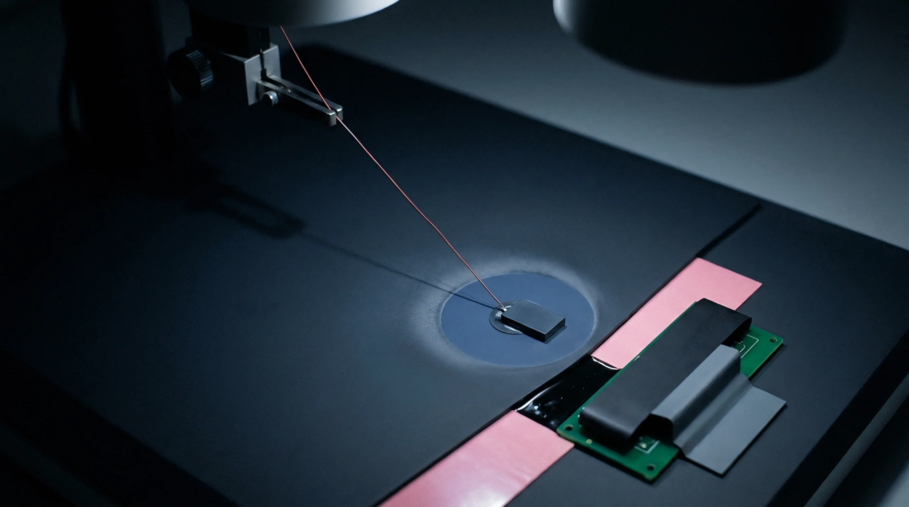
Field Measurement
Distributed electrical storage along a transmission line characterises the charge retention properties of high frequency circuits. Microstrip capacitance represents the electrostatic coupling between a conductive trace and a reference ground plane separated by a dielectric substrate. This parameter dictates signal propagation velocity and determines the characteristic impedance of the circuit path.
Design engineers calculate this value using the geometric dimensions of the trace width, the height of the substrate, and the relative permittivity of the insulating material.
Dielectric Influence
Material composition alters the electrostatic energy storage capacity within the structure. Permittivity variations across different frequency ranges introduce uncertainty in the calculated model. Manufacturers specify the dielectric constant within defined tolerance bands, yet manufacturing processes often shift these values from the nominal design intent.
Precise verification requires vector network analyzer measurements to observe phase shifts in test signals. Variations in local substrate thickness or minor surface irregularities add stray parasitic effects that complicate theoretical estimations.
Operational Performance
Signal integrity depends on maintaining consistent storage characteristics throughout the length of the conductor. Abrupt changes in trace geometry create impedance discontinuities that result in waveform distortion and energy loss at high frequencies. Proximity to adjacent traces generates mutual capacitive coupling that threatens to induce crosstalk in dense board layouts.
Controlled impedance routing protocols mitigate these risks by enforcing standard width requirements and spacing rules derived from the substrate properties. Electromagnetic field solvers provide the analytical rigour required to predict these interactions before fabrication.
Metrological Verification
Laboratory testing employs time domain reflectometry to isolate the storage characteristics of individual circuit segments. Technicians apply a fast rise time pulse to the line and analyze the reflected signal to identify impedance profiles along the conductive path. Variations from the theoretical baseline indicate fabrication defects or inaccurate material characterization.
Precision in this field requires calibration against known reference standards to eliminate systematic errors in the test apparatus. Accurate assessment of this metric ensures that high speed data transmission remains stable across varied environmental conditions.