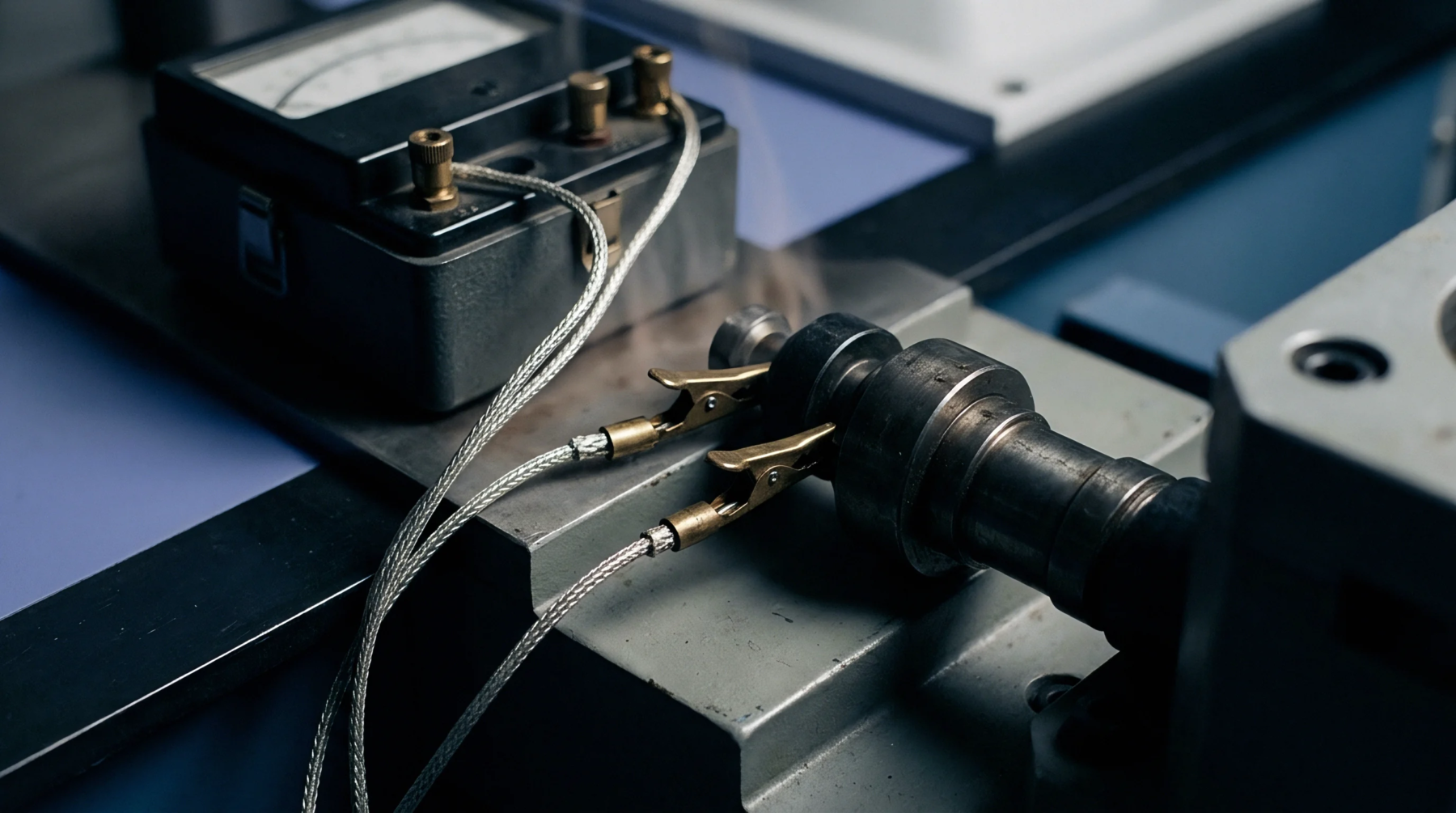
Null Detector
Precision resistance determination relies on a network of known and unknown resistors arranged to form a balanced circuit. This circuit configuration, termed a measurement bridge, enables the comparison of an unknown resistance to a reference standard with high accuracy. It minimizes the effect of lead resistance and voltage source fluctuations.
Electrical Balance
Ratio adjustment of the bridge arms is performed until the current flowing through the central detector is reduced to zero. In a standard measurement bridge, this state of balance occurs when the ratio of the two known arms equals the ratio of the unknown arm and the standard resistor. This method of comparison allows small fractional changes in resistance to be resolved.
Sensing Interface
Connection of a temperature-dependent sensor to the circuit converts the physical parameter into a measurable electrical signal. The measurement bridge is widely used with resistance temperature detectors where small resistance changes must be captured without adding self-heating errors. To prevent self-heating, the excitation current is kept as low as possible while still maintaining a detectable voltage across the bridge.
This balance is critical to prevent thermal errors in the sensor element during the measurement cycle.
Error Source
Parasitic thermoelectromotive forces and lead wire resistance can introduce errors in the measured value. Modern instruments mitigate these effects by using alternating current excitation or by rapidly reversing the direct current polarity. These techniques eliminate constant offset voltages from the measurement.