Geometric Specification
Printed circuit board designs specify the dimensions and spacing of copper pads to ensure reliable solder joint formation with electronic components. Establishing land pattern tolerances accommodates variation in component package dimensions and board fabrication limits. This standard defines the limits within which solder joints can form without causing electrical shorts or open circuits.
Solder Sourcing
Manufacturing yield decreases if the target dimensions of the copper pads diverge from the component specifications. When land pattern tolerances are set too loosely, solder can migrate away from the component terminal, causing a starved connection or a misaligned component. Conversely, overly tight tolerances can lead to solder bridging between adjacent fine-pitch pads.
Placement Precision
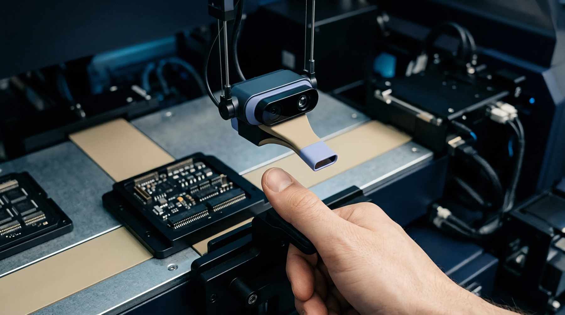
Automated placement machines use optical alignment systems to position components onto the solder-pasted pads with high precision. Designing within standard IPC guidelines ensures that the land patterns are optimized for the placement capabilities of the assembly line.
Mechanical Verification
Inspection laboratories use automated optical systems and microsectioning to verify the quality of the solder fillet against the defined limits. Sourcing boards from qualified fabricators ensures that the etching tolerances do not erode the engineered margins of the land design. This quality control loop is essential for high-reliability electronics used in industrial sensor environments.