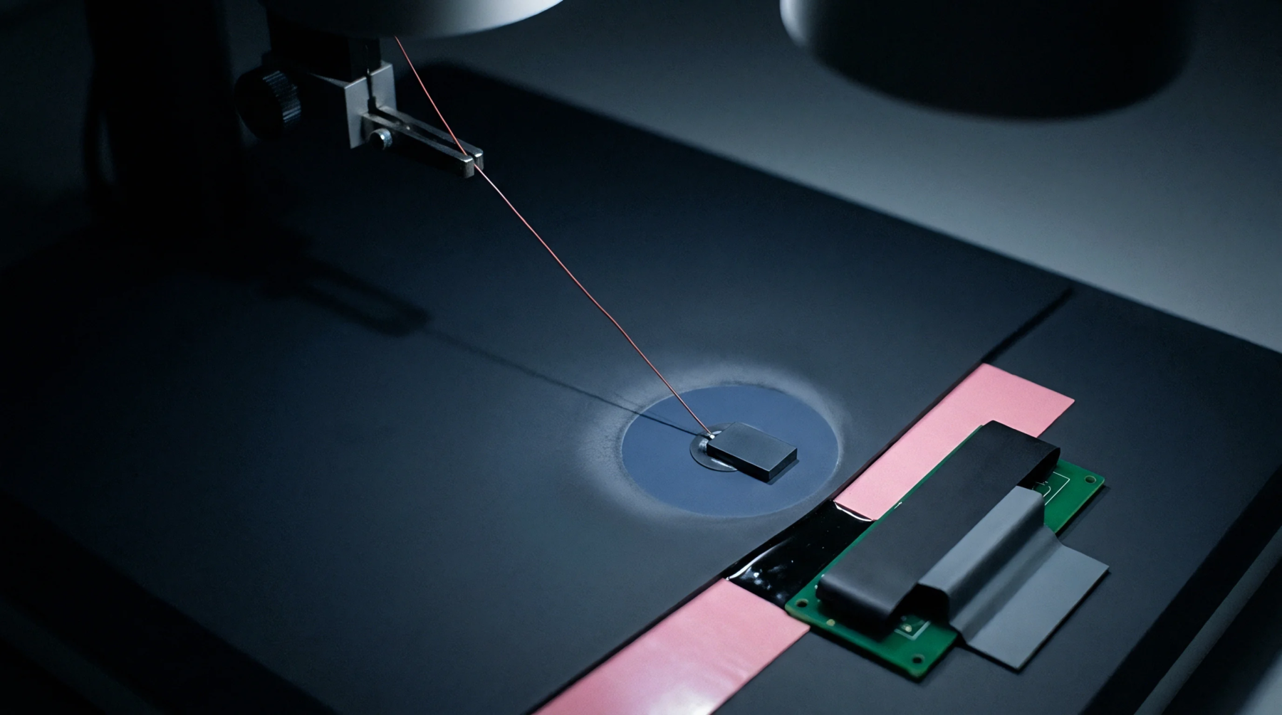
Bond Mechanics
Mechanical failure at a microscopic boundary during thermal cycling defines intermetallic compound shear. This metallurgical phenomenon occurs when brittle layers formed between copper and aluminum interfaces yield under differential expansion stresses. Laboratory shear tests quantify the force required to fracture these brittle zones per unit area.
Manufacturers measure bond strength against reference force standards maintained by national metrology institutes. Thermal fatigue during device operation accelerates crack propagation along the weakest plane of the joint. Calibration drift in automated bond testers introduces systematic errors that mask true interface brittleness.
Operators verify load cell accuracy monthly using dead weight primary standards to ensure compliance with published specifications. Environmental humidity during the wire bonding process promotes oxide growth and weakens the resulting alloy layer.
Thermal Stress
Temperature fluctuations induce cyclic strains that test the elastic limits of layered metal structures. Differing coefficients of thermal expansion between dissimilar conductors generate localized shear stresses at the microscopic interface. Excessive current loads produce joule heating which expands the base materials at disproportionate rates.
Extended exposure to elevated temperatures promotes atomic diffusion and thickens the vulnerable alloy zone over time. Thicker intermetallic layers exhibit reduced fracture toughness under mechanical loading conditions. Production engineers monitor reflow oven profiles to minimize the duration that components remain within peak formation temperature ranges.
Thermomechanical simulation software predicts stress distribution patterns across complex multi-layer interconnect architectures prior to physical prototyping.
Test Protocol
Destructive shear testing provides the primary metric for evaluating microelectronic interconnect integrity on production lines. Technicians position a calibrated chisel tool at a controlled height above the substrate to apply a horizontal force against the bonded ball or wedge. The test instrument records the peak force exerted at the exact moment of separation between the contact pads.
Acceptance thresholds depend on wire diameter and alloy composition as specified by international semiconductor assembly standards. Tool alignment errors introduce parasitic bending moments that artificially lower the recorded fracture force. Daily verification runs on gold reference samples confirm that tool wear has not compromised measurement repeatability.
Laboratories report peak force values in grams-force or Newtons alongside the specific failure mode observed under optical magnification.
Failure Analysis
Fracture surface examination reveals whether structural separation occurred cohesively through the alloy layer or adhesively at the interface. Scanning electron microscopy combined with energy dispersive X-ray spectroscopy identifies the elemental distribution across the fractured boundary. Brittle intermetallic compound shear typically leaves a smooth, featureless cleavage plane devoid of ductile deformation markings.
High void density within the alloy matrix severely degrades mechanical strength by reducing the effective load-bearing area. Corrective actions on wire bonders involve adjusting ultrasonic power, bonding force and stage temperature to optimize interface metallurgy. Final quality audits rely on statistical process control charts to track mean shear values and detect subtle shifts in manufacturing consistency before yield losses occur.