Component Geometry
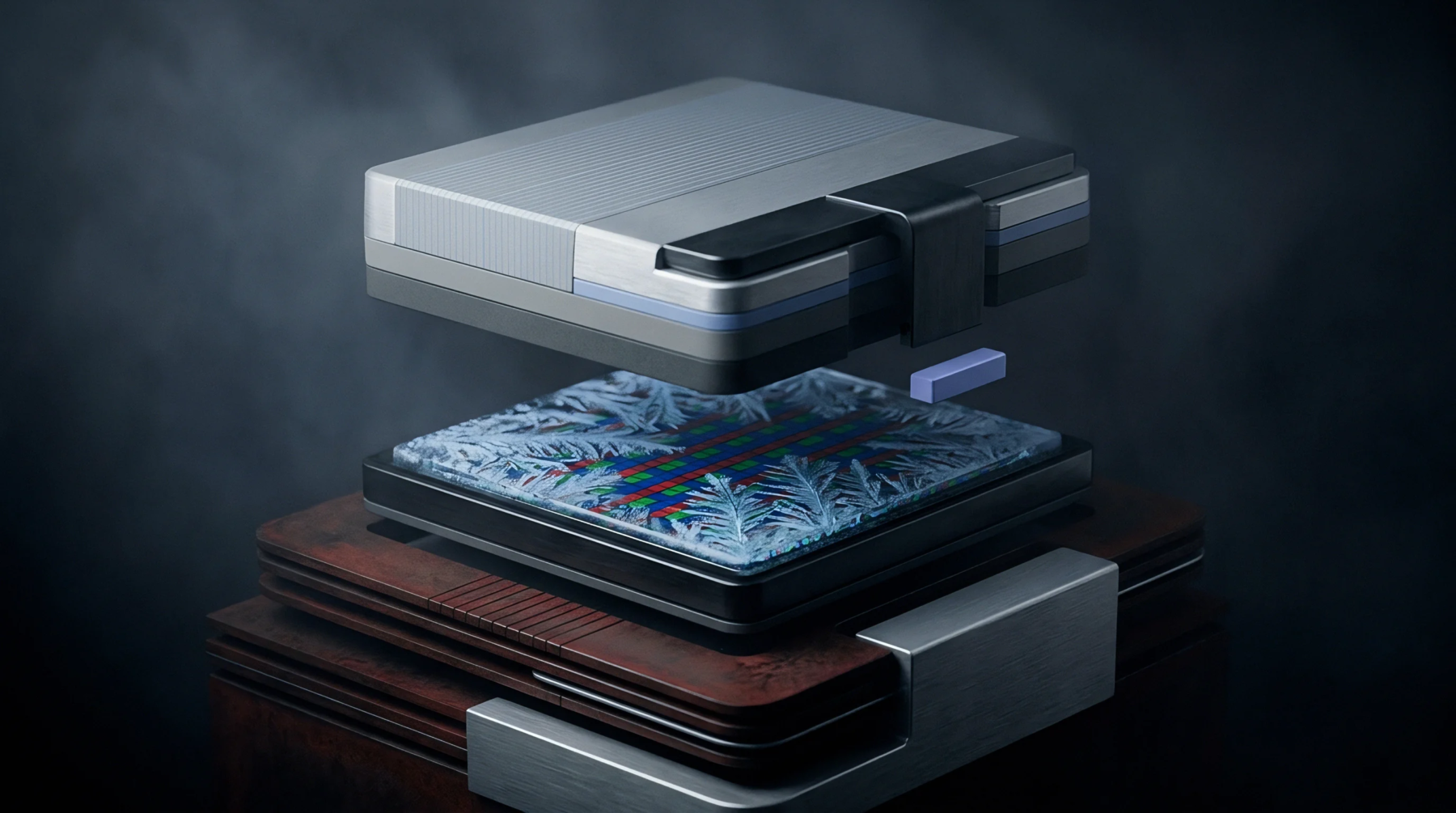
Rectangular electronic housing provides two parallel rows of electrical connecting pins for through-hole mounting to a printed circuit board. This dip configuration is a standard for integrated circuits that require manual handling or insertion into breadboards during the prototyping phase. The lead spacing is typically defined at 0.1 inches to match standard grid patterns.
Mechanical Housing
Protection of the internal silicon die is achieved through a plastic or ceramic body that resists thermal and mechanical stress. Within a dip, the internal bond wires connect the semiconductor chip to the lead frame which extends out of the package. This design allows for easy soldering and replacement without the specialized equipment needed for surface mount devices.
Thermal Performance
Heat dissipation occurs primarily through the pins and the body of the package into the surrounding air or the board. While the dip lacks the thermal efficiency of modern flat packs, it remains viable for low power applications and legacy systems. Larger versions of the package use more pins to distribute the electrical load and improve heat transfer.
Integration Context
Modern electronics often favor smaller footprints but the through hole nature of this package remains a requirement for rugged industrial controls. Assemblers use sockets to house the dip so that individual components can be swapped during maintenance or upgrades. The package remains a staple for logic gates and simple microcontrollers in education and repair because of its physical resilience and ease of identification.
High reliability environments sometimes specify ceramic variants to handle extreme temperature ranges.