Minimum Boundary
Geometric limits establish the lowest allowable curve for flexible printed circuits or cables without causing physical or electrical degradation. The bend radius of a flexible assembly determines how much the substrate can fold during installation or dynamic operation. Below this threshold, copper traces experience excessive strain, leading to microcracking or immediate failure.
Measurement of this parameter depends on the thickness of the dielectric and the weight of the copper foil.
Stress Calculation
Mathematical equations define the outer fiber strain as a function of the thickness ratio of the materials. When calculating the bend radius, engineers relate the total thickness of the flexible circuit to the acceptable percentage of strain for a given copper alloy, which prevents early material fatigue. Dynamic applications require a much larger ratio than static installations to avoid fatigue failures over millions of cycles.
Standard calculations assume a neutral axis located at the geometric center of the cross-section, though this axis shifts when asymmetric ground planes or thick coverlays are introduced into the stackup design.
Verification Procedure
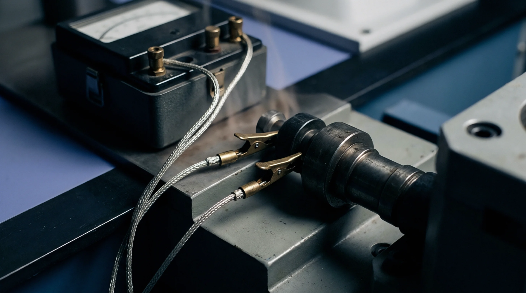
Mechanical fixtures assess conformance by wrapping the specimen around a polished mandrel of known diameter. This test confirms that the bend radius meets the specified limit without causing circuit discontinuity or delamination. Automated testing stations monitor resistance continuously during cyclic flexing to capture transient opens that indicate microfractures.
Calibration Standard
Certified gauge blocks verify mandrel diameters to guarantee traceablity. Dimensional tolerances remain tight to ensure repeatability.