Temporal Latency
Signal transmission speed defines the interval between the application of an input current and the corresponding transition of the output voltage state. Optocoupler propagation delay represents the period required for the internal light emitting diode to convert electricity into photons and for the photodetector to register that pulse. This measurement spans from the fifty percent point of the input waveform to the fifty percent point of the output waveform.
Variations in internal capacitance and base emitter resistance dictate the speed of these switching transitions.
Output Symmetry
Changes in temperature affect the transit speed of optocoupler propagation delay by altering the carrier mobility within the silicon junctions. Elevated heat increases the charge recombination time which causes the timing to drift beyond the nominal rating specified at twenty-five degrees Celsius. Designers compensate for this by selecting drive currents that force the output transistor into saturation quickly.
Loading conditions exert a dominant influence on the fall time relative to the rise time. High impedance nodes lengthen the discharge path and stretch the duration of the signal shift.
Measurement Protocol
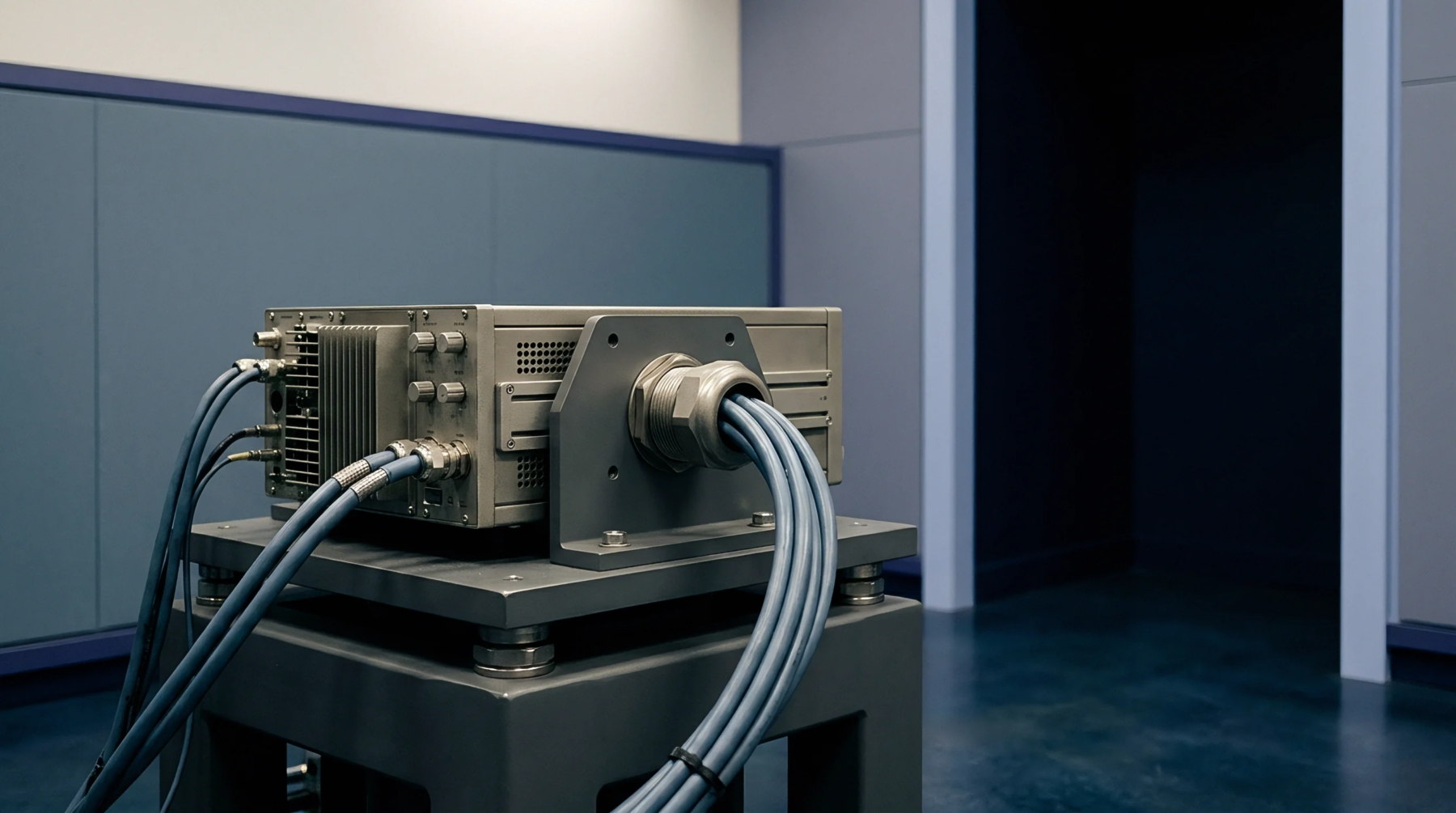
Verification of these specifications occurs within test fixtures designed to minimize stray inductance across the input and output terminals. Oscilloscope probes with low capacitance prevent the measurement equipment from loading the collector circuit during high speed switching events. Current source generators provide the precisely controlled input pulses needed to stabilize the start point of the timing interval.
Calibration of the test setup requires a known reference standard to account for the internal delay of cables and interconnects. Accuracy depends upon the rise time of the pulse generator matching or exceeding the speed of the device under test.
Component Tolerance
Variations between manufacturing lots produce discrepancies in switching speed that exist even within the same product family. Semiconductor manufacturers establish the maximum allowable latency at specific collector currents and load resistor values. Data sheets define these boundaries to inform the timing budget of high speed communication links and isolated control interfaces.
Designers must select devices that maintain consistent timing performance across the full range of expected operating currents. Proper selection of passive biasing components fixes the switching characteristic of the circuit.