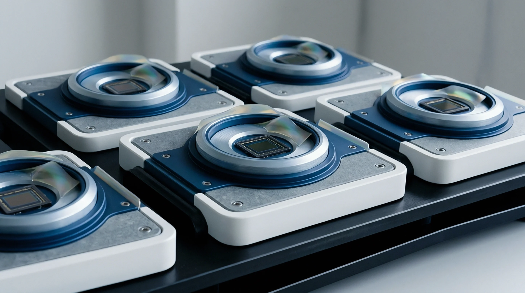
Register Maps That Moved at a Die Revision Nobody Announced
Unannounced die shrinks alter internal register maps and bus timing; enforce strict automated register fingerprinting and binding PCN contract terms.
Output circuity logic employs a complementary pair of transistors to actively pull an electrical line high to VCC or low to ground as needed. This active push pull driver ensures that signal transitions are sharp and fast because the circuit does not rely on a passive resistor to return to its original voltage. Using a push pull driver provides low impedance in both logic states, which effectively resists the effects of electromagnetic noise on the transmission cable.
In most high performance sensor interfaces, a push pull driver is chosen to drive the data lines at high megahertz frequencies without signal rounding or edge jitter. Because the power consumption is limited mostly to the switching transitions, it offers higher efficiency for logic levels that cycle frequently during serial communication.
Current sourcing limits determine the maximum distance a push pull driver can transmit clear signals before inductive or capacitive losses start to distort the information. Most microcontrollers integrate a push pull driver on their generic input output pins to provide direct control for external digital devices without needing buffer chips. When a push pull driver switches state, it provides a direct path for current to flood the line, enabling it to overcome the capacitance of the trace almost immediately.
Testing labs verify that the rise and fall times of a push pull driver meet the interface specification under typical load resistance values at standard temperatures. If multiple participants share a bus, a push pull driver cannot be used directly because two active switches might fight, creating a high current short.
Timing analysis helps quantify the delay introduced by a push pull driver when shifting from a logical zero to a logical one in high speed processors. Heat generation within the push pull driver stays relatively low unless the drive frequency increases into the hundreds of megahertz range where switching losses become significant. Designers select these components for point to point serial links like SPI or high speed clock lines where only one device controls the voltage at a time.
The stability of a push pull driver ensures that logic thresholds are consistently reached, which simplifies the error correction needed in the receiver software. Any fluctuation in the power supply voltage typically translates directly into the output level of the push pull driver unless a local regulator is present.
Termination resistors are sometimes combined with a push pull driver to prevent signal reflections that occur at the end of long electrical wires. Because the internal impedance of a push pull driver is very low, any mismatch in line impedance can cause energy to bounce back toward the sensor, creating phantom data spikes. Correct calibration of these circuits involves adjusting the transistor width during the initial silicon design to balance power usage against drive strength.
Most hardware specialists confirm the signal integrity of a push pull driver using high bandwidth oscilloscopes before finalizing a new printed circuit board layout. Maintaining these exact voltage profiles ensures that electronic components across the system talk to each other without missing critical bit updates during operations.
Unannounced die shrinks alter internal register maps and bus timing; enforce strict automated register fingerprinting and binding PCN contract terms.
Expertise is a utility, not a secret. sentiention™ publishes its working knowledge as open reference: intelligence layer covering the materials it sources, the markets it enters, and the reference that serves both.