Thermal Balancing
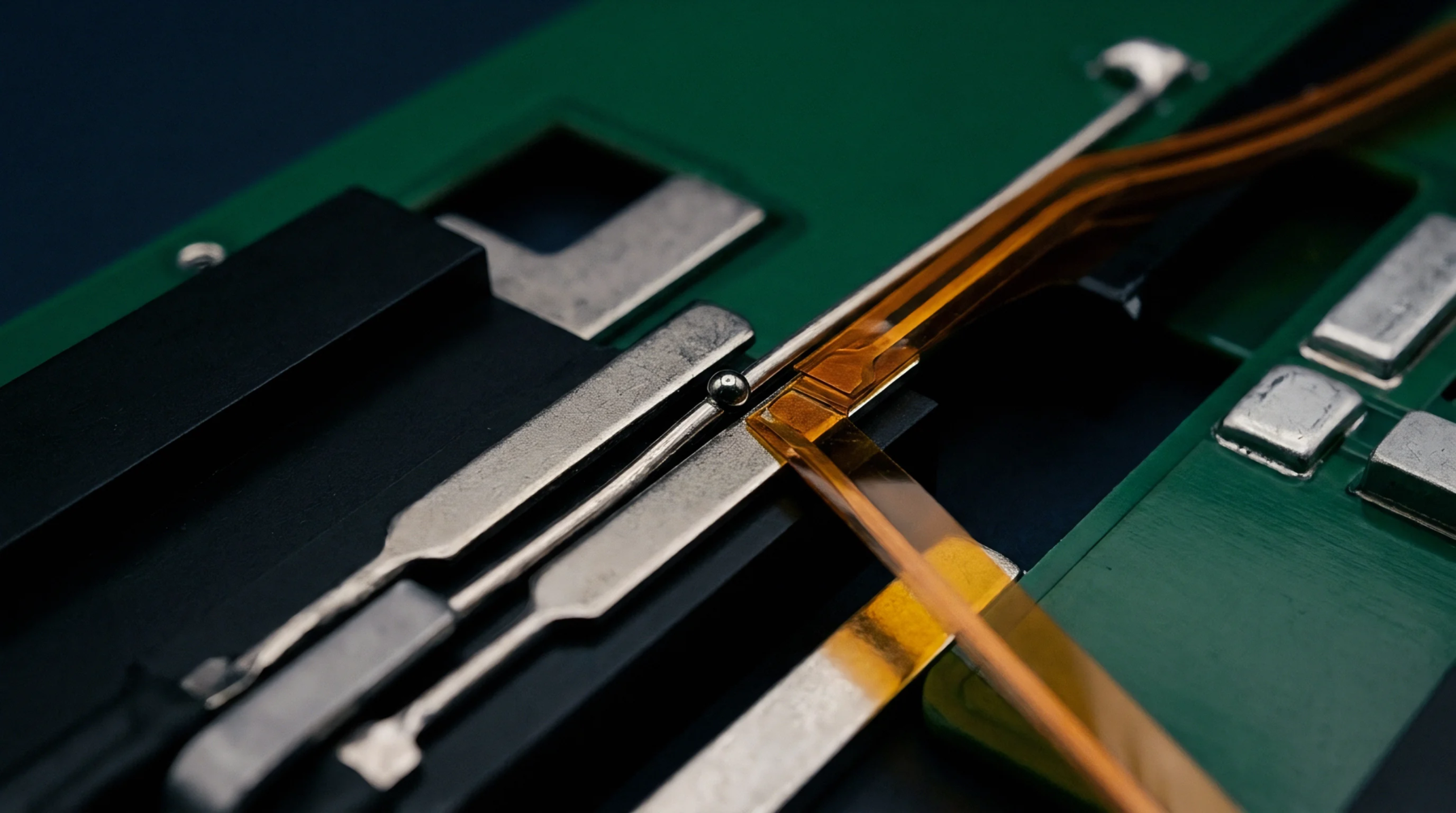
Printed circuit configurations ensure that specific conductive paths maintain identical temperatures to prevent measurement errors caused by thermocouple effects. Implementing an isothermal trace layout places matching copper runs in the same orientation relative to local heat sources. This technique stabilizes sensitive signals in precision data acquisition units.
Placement Strategy
Geometric distance from high power components creates steady temperature gradients across the board surface. The isothermal trace layout forces heat to reach both parallel signals at the exact same moment and magnitude. Engineers use this symmetry to cancel out voltages induced by the Seebeck effect at component junctions.
Signal Precision
Trace thickness and copper weight contribute to how energy moves through the signal path during high activity. In an isothermal trace layout, the identical pathing ensures that common mode rejection handles any drift triggered by the ambient environment. Typical tolerances target differences smaller than one tenth of a degree Celsius.
Layout Validation
Infrared cameras confirm that temperatures remain equal along the defined paths during full operation. Any isothermal trace layout that fails to account for internal plane heating will introduce millivolt errors that standard filtering cannot detect. Proper implementation fixes the zero point in weighing scales and high resolution voltage meters.