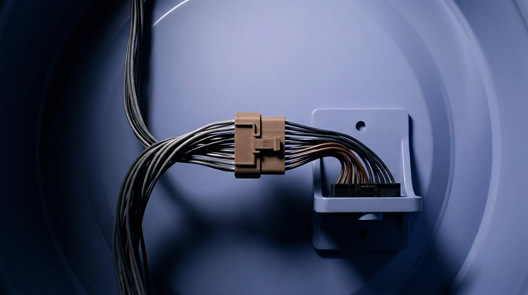
Hardware Configuration
Circuit board design utilizes physical pin connections to establish fixed device identifiers upon power-up. This method, known as address strapping, assigns unique communication paths by hardwiring select pins of an integrated circuit to either power or ground.
Electrical Implementation
Resistors connected in pull-up or pull-down configurations hold the designated pins at stable voltage levels during the system initialization phase. These pull-up or pull-down resistors prevent floating inputs from causing fluctuating states on startup. Once the device boots, the internal logic reads the static voltage levels of the strapped pins to set its digital identifier.
Signal Level
Static voltage ranges on the pins correspond directly to binary digits. A high logic level represents a binary one, while a ground connection registers as a binary zero. The microcontroller or sensor reads these binary values during the reset sequence, which determines its address on the shared communications bus.
In this way, multiple identical chips can operate on the same bus without addressing conflicts. Since the assignment is determined entirely by PCB routing, it remains immune to firmware modifications or software exploits.
Design Choice
Hardwired configurations offer a permanent and cost-effective solution compared to software-programmable registers. It eliminates the need for non-volatile memory to define the identity of the chip. This approach minimizes startup complexity.