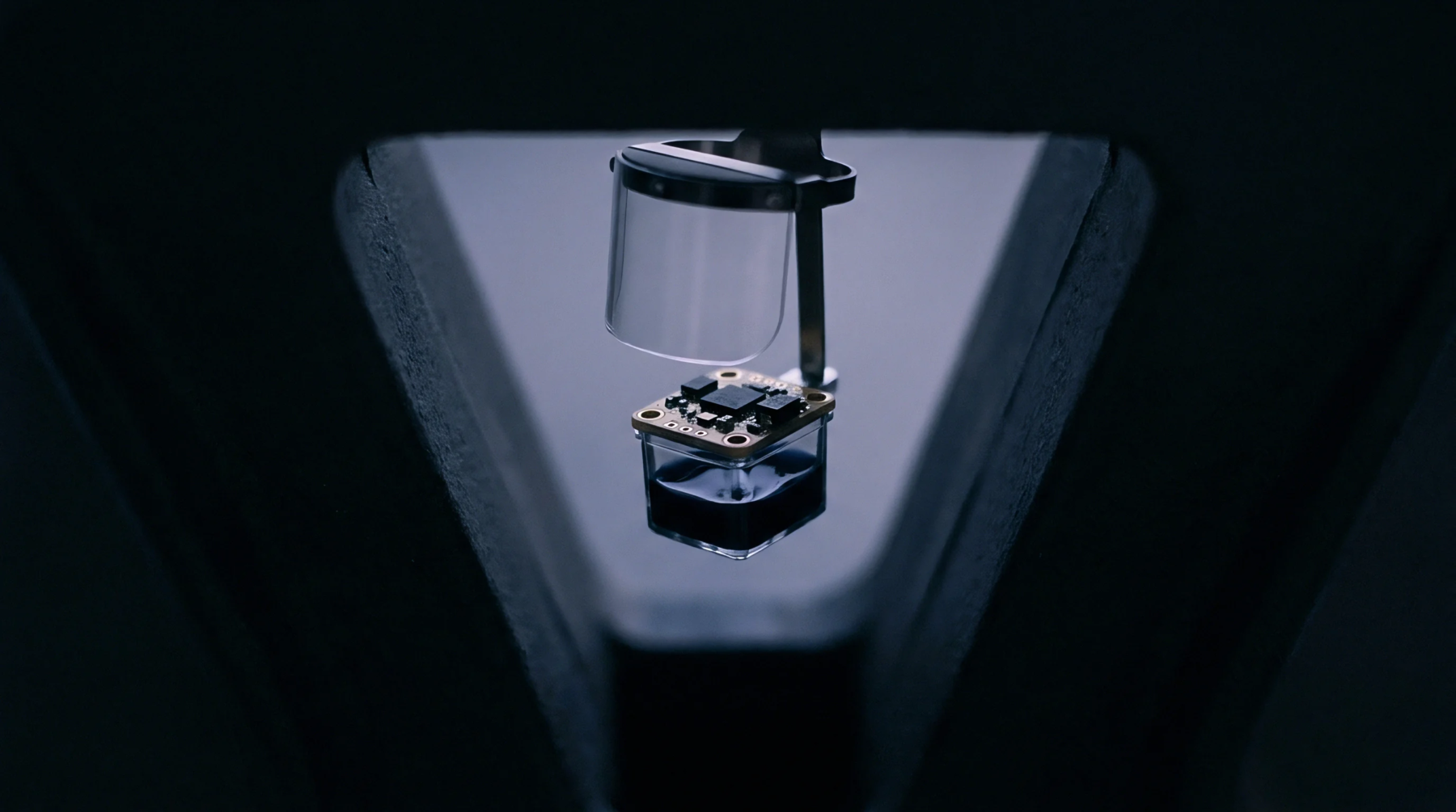
Electrical Circuit
High-frequency circuit loops require a continuous route for the current to flow from the load back to the source. The geometric route of the return path determines the loop inductance and electromagnetic emissions of the system. This path must be carefully designed to prevent noise coupling.
Current Distribution
At high frequencies, the return current takes the path of least inductance, which is directly beneath the signal trace. This distribution is different from low-frequency currents that follow the path of least resistance. This distinction is critical for circuit design.
Impedance Discontinuity
When a signal trace transitions between board layers without a nearby ground via, the path of the return current is interrupted. This interruption creates an impedance mismatch that causes signal reflections and noise. Providing ground return vias next to signal vias offers a continuous path for the current.
This layout technique minimizes electromagnetic interference and maintains signal integrity across the circuit board. It is a standard practice in high-speed PCB design.
Layout Protocol
Design rules require that ground and power planes are continuous and free of slots or splits beneath high-speed signals. This routing protocol prevents the return path from spreading out and coupling with adjacent traces.